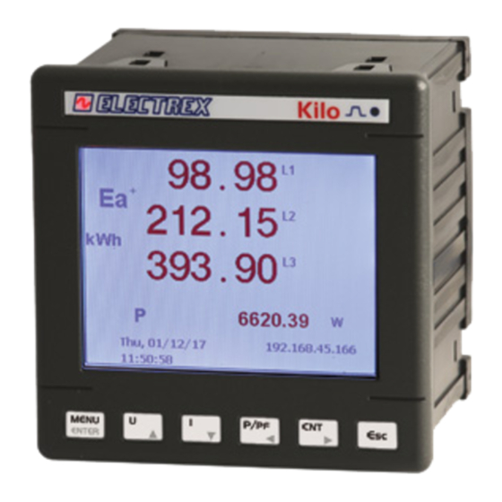
Electrex EXA 96 Manuale di installazione - Pagina 4
Sfoglia online o scarica il pdf Manuale di installazione per Strumenti di misura Electrex EXA 96. Electrex EXA 96 4.
Anche per Electrex EXA 96: Manuale di installazione (4 pagine)

Voltage connection: Use cables with max cross-section of 2,5 mm
to the applicable diagrams that follow.
Current connection: It is necessary to use external CTs with a primary rating adequate to the load to be measured and with a 5A or 1A secondary rating. Connect the CT output(s) to
the terminals marked I1, I2, I3 (CURRENT INPUT) of the instrument according to the applicable diagrams that follow. Use cables with cross-section adequate to the VA rating of the CT
and to the distance to be covered. The max cross-section for the terminals is 2,5 mm
Note: The CT secondary must always be in short circuit when not connected to the instrument in order to avoid damages and risks for the operator.
Scrupulously respect the matching of phase between the voltage signals and current signals (RTD) and the direction of insertion of CT (P1-P2 and S1-S2). Failure to comply with this
correspondence and connection diagrams gives rise to measurement errors. (*) The grounding of S2 must be close to the CT and not near the instrument.
STAR 4W (4 WIRES) 3PH-4W LV
P1
P2
L1
S1
S2
P1
P2
L2
S1
S2
P1
P2
L3
S1
S2
N
S1 S2 S1 S2 S1 S2
I1
I2
I3
CURRENT INPUTS
EXPBUS
POWER
VOLTAGE INPUTS
SUPPLY
V1 V2 V3 N
17
TRIANGLE 3W (3 WIRES ) 3PH-3W
P1
P2
L1
S1
S2
P1
P2
L2
S1
S2
P1
P2
L3
S1
S2
S1 S2 S1 S2 S1 S2
I1
I2
I3
CURRENT INPUTS
EXPBUS
POWER
VOLTAGE INPUTS
SUPPLY
V1 V2 V3 N
17
TRIANGLE 2CT(3 WIRES ) 3PH-3W MV
P1
P2
L1
S1
S2
L2
P1
P2
L3
S1
S2
S1 S2 S1 S2 S1 S2
I1
I2
I3
CURRENT INPUTS
EXPBUS
POWER
VOLTAGE INPUTS
SUPPLY
V1 V2 V3 N
17
akse srl Via Aldo Moro, 39 42124 Reggio Emilia Italy
Tel. +39 0522 924 244 Fax +39 0522 924 245 [email protected] www.akse.it
P.I. 01544980350 R.E.A. 194296
VOLTAGE AND CURRENT CONNECTION
2
if stranded 4 mm
L1
L2
L3
10 11
12
19
20
21
AUX IN/OUT
ETHERNET
RS-485
18
A B
L1
L2
10 11
12
19
20
21
AUX IN/OUT
ETHERNET
RS-485
18
A B
10 11
12
19
20
21
AUX IN/OUT
ETHERNET
RS-485
A B
18
Cap. Soc. Euro 85.800,00 i.v.
2
if rigid and connect them to the clamps marked VOLTAGE INPUT on the instrument according
2
if stranded and 4 mm
2
if rigid.
STAR 4W (4 WIRES) 3PH-4W MV
P1
P2
S1
S2
P1
P2
S1
S2
P1
P2
S1
S2
S1 S2 S1 S2 S1 S2
10 11
12
19
20
I1
I2
I3
AUX IN/OUT
CURRENT INPUTS
EXPBUS
ETHERNET
POWER
RS-485
VOLTAGE INPUTS
SUPPLY
V1 V2 V3 N
17
18
A B
BI-PHASE (2 WIRES ) 2PH-2W
P1
P2
S1
S2
S1 S2 S1 S2 S1 S2
10 11
12
19
20
I1
I2
I3
AUX IN/OUT
CURRENT INPUTS
EXPBUS
ETHERNET
POWER
RS-485
VOLTAGE INPUTS
SUPPLY
V1 V2 V3 N
17
18
A B
The instrument is fi tted with a separate power supply. The power supply terminals are
numbered (17 e 18). Use cables with max cross-section of 2,5 mm
rigid.
SINGLE PHASE (2 WIRES) 1PH-2W
L1
N
21
TRIANGLE 2CT (3 WIRES ) 3PH-3W
L1
L2
L3
21
POWER SUPPLY
S1 S2 S1 S2 S1 S2
10 11
12
19
I1
I2
I3
AUX IN/OUT
CURRENT INPUTS
EXPBUS
ETHERNET
POWER
VOLTAGE INPUTS
SUPPLY
V1 V2 V3 N
17
18
FUSE
85 ÷ 265 V ±10%
(500mA T)
N
L
P1
P2
S1
S2
S1 S2 S1 S2 S1 S2
10 11
12
19
20
21
I1
I2
I3
AUX IN/OUT
CURRENT INPUTS
EXPBUS
ETHERNET
POWER
RS-485
VOLTAGE INPUTS
SUPPLY
V1 V2 V3 N
17
18
A B
P1
P2
S1
S2
P1
P2
S1
S2
S1 S2 S1 S2 S1 S2
10 11
12
19
20
21
I1
I2
I3
AUX IN/OUT
CURRENT INPUTS
EXPBUS
ETHERNET
POWER
RS-485
VOLTAGE INPUTS
SUPPLY
V1 V2 V3 N
17
18
A B
if stranded, 4 mm
if
2
2
20
21
RS-485
A B
Engineered and manufactured in Italy
Made
in
Italy
Pensato, progettato e prodotto in Italia
Subject to modifi cation without notice.
Edition 2017 05 02 ENG0137
