Baumer HUBNER BERLIN HOG 10 Istruzioni per il montaggio e il funzionamento - Pagina 18

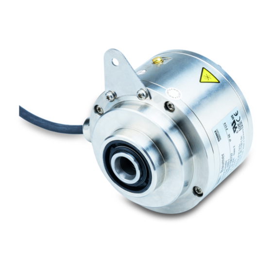
Sfoglia online o scarica il pdf Istruzioni per il montaggio e il funzionamento per Convertitore multimediale Baumer HUBNER BERLIN HOG 10. Baumer HUBNER BERLIN HOG 10 36. Incremental encoder with connecting cable ölfle
Anche per Baumer HUBNER BERLIN HOG 10: Manuale di installazione e istruzioni per l'uso (36 pagine), Manuale di installazione e istruzioni per l'uso (40 pagine), Istruzioni per il montaggio e il funzionamento (40 pagine), Manuale di installazione e istruzioni per l'uso (40 pagine), Istruzioni per il montaggio e il funzionamento (40 pagine), Istruzioni per il montaggio e il funzionamento (40 pagine), Istruzioni per il montaggio e il funzionamento (32 pagine), Istruzioni per il montaggio e il funzionamento (36 pagine), Istruzioni per il montaggio e il funzionamento (28 pagine)

Baumer HUBNER BERLIN HOG 10 Istruzioni per il montaggio e il funzionamento
5
Montage / Mounting
5.8
Hinweis zur Vermeidung von
Messfehlern
Für einen einwandfreien Betrieb des
Gerätes ist eine korrekte Montage, ins-
besondere auch der Drehmomentstütze,
notwendig, wie beschrieben in Abschnitt
5.1 bis 5.7.
Der Rundlauffehler der Antriebswelle
sollte möglichst nicht mehr als 0,2 mm
(0,03 mm empfohlen) betragen, da hier-
durch Winkelfehler verursacht werden.
Solche Winkelfehler können durch einen
größeren Abstand L1 reduziert werden
Dabei ist zu beachten, dass die Länge L2
der Drehmomentstütze, siehe Abschnitt
5.7, mindestens gleich L1 sein sollte
Der Winkelfehler kann wie folgt berechnet
werden:
= ± 90°/π · R/L1
Δρ
mech
mit R:
Rundlauffehler in mm
L1:
Abstand der Drehmomentstütze zum
Gerätemittelpunkt in mm
Berechnungsbeispiel:
Für R = 0,06 mm und L1 = 69,5 mm ergibt
sich ein Winkelfehler Δρ
Auf Anfrage sind hierzu verschiedene Stützbleche für die
4)
Drehmomentstütze erhältlich.
Wenn L2 < L1 muss mit der Länge L2 gerechnet werden.
5)
i
Weitere Informationen erhalten Sie
unter der Telefon-Hotline
+49 (0)30 69003-111
15
5)
von ± 0,025°.
mech
Baumer_HOG10-HOG10G-Cannon_T1_DE_EN_202202_MI_11145663 (22A1)
5.8
How to prevent measurement errors
To ensure that the device operates cor-
rectly, it is necessary to mount it accu-
rately as described in section 5.1 to 5.7,
which includes correct mounting of the
torque arm.
The radial runout of the drive shaft should
not exceed 0.2 mm (0.03 mm recom-
mended), if at all possible, to prevent an
angle error.
An angle error may be reduced by
.
increasing the length of L1
4)
that the length L2 of the torque arm, see
section 5.7, is at least equal to L1
.
The angle error can be calculated as
follows:
Δρ
mech
with R:
Radial runout in mm
L1:
Distance of the torque arm to the center
point of the device in mm
Example of calculation:
For R = 0.06 mm and L1 = 69.5 mm the
resulting angle error Δρ
± 0.025°.
For this different support plates for the torque arm are
4)
available on request.
If L2 < L1, L2 must be used in the calculation formula.
5)
i
For more information,
call the telephone hotline at
+49 (0)30 69003-111
4)
= ± 90°/π · R/L1
mech
MB045T1 - 11145663
. Make sure
.
5)
equals