Baumer Hubner Berlin PMG10 Manuale operativo - Pagina 2
Sfoglia online o scarica il pdf Manuale operativo per Convertitore multimediale Baumer Hubner Berlin PMG10. Baumer Hubner Berlin PMG10 44. Absolute encoder
Anche per Baumer Hubner Berlin PMG10: Istruzioni per il montaggio e il funzionamento (32 pagine), Istruzioni per il montaggio e il funzionamento (32 pagine)
List of contents
List of contents
1 About this document...................................................................................................................................
1.1
Purpose ..............................................................................................................................................
1.2
Warnings in this manual .....................................................................................................................
1.3
Labels in this manual ..........................................................................................................................
1.4
Disclaimer ...........................................................................................................................................
1.5
Scope of delivery ................................................................................................................................
1.6
Name plate .........................................................................................................................................
1.7
Maintenance and service life ..............................................................................................................
1.8
Approvals and warranty ......................................................................................................................
1.9
Temperature range for operation and storage....................................................................................
2 General information ....................................................................................................................................
3 Transport and storage ................................................................................................................................
3.1
Transport ............................................................................................................................................
3.2
Delivery inspection..............................................................................................................................
3.3
Storage ...............................................................................................................................................
4 Description...................................................................................................................................................
4.1
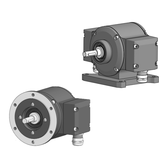
Rotary encoder ...................................................................................................................................
4.2
Mounting accessories (not included) .................................................................................................. 10
4.3
Required tools..................................................................................................................................... 10
5 Installation.................................................................................................................................................... 11
5.1
Mounting with EURO flange B10 ........................................................................................................ 11
5.1.1
Attach coupling onto encoder shaft....................................................................................... 11
5.1.2
Mounting encoder onto drive shaft........................................................................................ 12
5.2
Mounting with base B3 ....................................................................................................................... 14
5.2.1
Attach coupling onto encoder shaft....................................................................................... 14
5.2.2
Mounting encoder onto drive shaft........................................................................................ 15
5.3
washer ................................................................................................................................................
5.4
Notes when using a claw coupling (e.g. ROTEX®) ............................................................................ 18
6 Electrical installation................................................................................................................................... 19
6.1
Connections........................................................................................................................................ 20
6.2
SSI interface ....................................................................................................................................... 21
6.2.1
Data transfer ......................................................................................................................... 21
6.2.2
"RESET" function .................................................................................................................. 21
6.2.3
Function Direction of rotation ................................................................................................ 21
6.3
Output signals additional incremental output (optional)...................................................................... 22
6.4
Switching level additional output incremental (optional) ..................................................................... 22
6.5
Programming interface (only for programmable variant) .................................................................... 22
ii
Operating Manual
Baumer Hübner
PMG10 & PMG10P SSI | V1
4
4
4
4
4
5
5
5
5
6
7
8
8
8
8
9
9
17