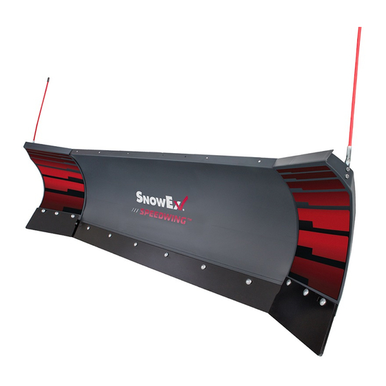
Douglas Dynamics SnowEx Automatixx SPEEDWING 77740 Manuale di istruzioni per l'installazione - Pagina 5
Sfoglia online o scarica il pdf Manuale di istruzioni per l'installazione per Spazzaneve Douglas Dynamics SnowEx Automatixx SPEEDWING 77740. Douglas Dynamics SnowEx Automatixx SPEEDWING 77740 17.

UNPACKING AND REMOVING SHIPPING
BRACKETS
1. Set aside the blade guides and parts bags. The
vehicle electrical harnesses and Owner's Manual
packet are in the bag with the headlamp box.
Move the attach/detach lever to unpin the
receivers and set aside.
NOTE: Leave handle in the detach position during
entire assembly process.
2. Remove the lag screws and wood blocks securing
the headlamp channel to the headgear and set the
headlamp channel aside.
3. Remove the packaging hardware securing the
headgear to the A-frame, except for the clevis pins
and the shipping brackets.
4. Remove the fasteners and blocking securing the
A-frame to the pallet.
5. While supporting the headgear, remove and retain
the clevis pins and discard the shipping brackets
and hairpin cotters. Remove and discard the
shipping brackets and cap screw and locknut from
the lift cylinder.
Remove and discard
shipping brackets (both sides).
Remove and discard
cap screw and locknut.
Remove and retain
1" x 4" clevis pins.
Lit. No. 52308, Rev. 06
INSTALLATION INSTRUCTIONS
Remove
and retain
1" x 4-3/4"
clevis pin.
A-FRAME HOLE POSITION
IMPORTANT! Before assembling headgear to
A-frame, measure the vehicle mount height to
confi rm whether standard receivers or tall receivers
are required, and which A-frame holes to use for
installation. (If the truck is not available, use the
middle position. Make any adjustments later.)
Before measuring the vehicle mount height, the mount
must be installed on the vehicle, ballast (if required)
must be installed, and the vehicle must be parked on a
level surface.
1. Measure the distance "d" from the ground to the
center of the hole in the vehicle mount. Measure
the distance on both sides of the vehicle and
determine average value for "d."
d
2. Use the following chart to determine the proper
hole position.
A-Frame Hole Position Chart
Distance "d"
11.5" – 13.0"
13.0" – 14.5"
14.5" – 16.5"
16.5" – 18.5"
Tall receivers (85121 & 85122) required in
†
place of standard receivers.
5
Center of Hole
in Vehicle Mount
Hole Position
Bottom
Middle
Top
Top
†
Top
Middle
Bottom
May 1, 2021
