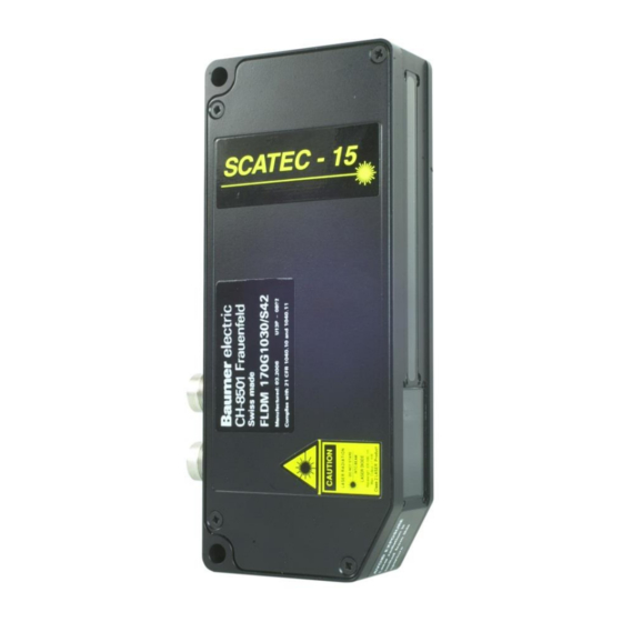
Baumer FLDM 170G1030/S42 Manuale d'uso - Pagina 8
Sfoglia online o scarica il pdf Manuale d'uso per Sportello di cassa Baumer FLDM 170G1030/S42. Baumer FLDM 170G1030/S42 44. Laser copy counter

6 Terms and definitions
Scatec-1x
k
Front edge
Mounting height
h
Working distance
d
Overlap
a
Edge thickness
k
Front edge
Tail edge
Running direction
Interfering edge
User manual Scatec-10 / -15
Version 2017-10
h
d
Beam blocker
Distance between the lower edge of the sensor and the conveying plane.
Distance between the lower edge of the sensor and the plane where the edge
lies on. Note that the working distance equals the mounting height only if the
edge lies directly on the conveying plane.
Interval between two successive edges, measured along the conveying plane.
Thickness of the copy at the point where the edge is to be detected.
The edge of an object which faces the laser beam. In principle, edges facing
the laser beam can be detected
by the Scatec, independently of
the running direction.
The edge of an object which
faces away from the laser beam.
Edges facing away from the
laser beam cannot be detected
by the Scatec and do not initiate
output pulses no matter the
running direction is.
For Scatec-10 / -15 both running
directions are allowed, with the
front edge leading (a) or trailing
(b). A front edge is detected
independently
of
direction. However, for certain
false pulse suppression modes to
operate properly, the running
direction must be set correctly.
Folds, fissures, creases, or other imperfections on a newspaper can form
edges which will be detected by the Scatec but should not be counted. Such
edges are termed "interfering edges" and cause so called "false pulses".
Scatec-10 / -15 offers several possibilities to efficiently suppress these false
pulses.
www.baumer.com
Running direction
a
Tail edge
Laser beam
Front edge:
detectable
Laser beam
the
running
8 / 44
Conveying plane
Interfering edge
Tail edge:
non-detectable
Running direction of copy:
(a) leading
(b) trailing
Baumer Electric AG
Frauenfeld, Switzerland
