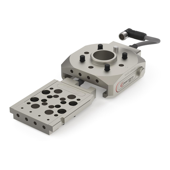
Dover DESTACO TC1-050-T-02 Manuale di servizio - Pagina 11
Sfoglia online o scarica il pdf Manuale di servizio per Apparecchiature industriali Dover DESTACO TC1-050-T-02. Dover DESTACO TC1-050-T-02 16.

TC1 TOOL CHANGER
Service Manual
3. Electric Modules
Electric power and signal modules are available in various configurations. See Table 4 for compatibility
with master and tool plates.
ITEM
PART NUMBER
1
TC1-E01M-C01
2
TC1-E01T-C01
3
3
TC1-E01T-N01
Electric Module Replacement
1.
the electric modules. Servicing or maintaining the tool changer without isolating it from pneumatic and
electric power sources may result in electric shock and personal injury.
2. Remove the existing electric module by disconnecting the electrical connector and unscrewing the M3
screws using 2.5mm hex key wrench (see Fig.9 or Fig.10).
3. Place the new electric module in the same position, apply Loctite 242, 243, or equivalent to the screws
and tighten to 0.9 Nm using the 2.5mm hex key wrench. Reconnect the electrical connector.
8 PIN M8 SOCKET ELECTRICAL PASS-THRU MASTER MODULE
8 PIN M8 PLUG ELECTRICAL PASS-THRU TOOL MODULE
TC1-E01T-P01
PNP MAGNETO RESISTIVE 4MM SENSING MODULE
NPN MAGNETO RESISTIVE 4MM SENSING MODULE
Remove all pneumatic and electric power sources from the tool changer before servicing
MASTER
PLATE
THREAD LOCKER
TABLE 4
DESCRIPTION
MASTER ELECTRICAL
MODULE
M3 FLAT HEAD
SCREW
2.5mm HEX KEY WRENCH
Fig.9
9
COMPATIBILITY
TC1-050M-XX
TC1-050T-XX
0.9Nm
9
TC1
Service Manual
Rev. A
24 Nov 2020
