Dover OPW 623V Series Istruzioni per l'installazione e la manutenzione - Pagina 2
Sfoglia online o scarica il pdf Istruzioni per l'installazione e la manutenzione per Unità di controllo Dover OPW 623V Series. Dover OPW 623V Series 4. Pressure / vacuum vent valve

restricted access to the product and the site. This limited war-
ranty also shall not apply to any product which has been al-
tered in any way, which has been repaired by anyone other
than a service representative authorized by OPW, or when
failure or defect is due to: improper installation or mainte-
nance (including, without limitation, failure to follow Flex-
Works Quick Reference Manual Installation Guide and all
product warning labels); abuse or misuse; violation of health
or safety requirements; use of another manufacturer's, or
otherwise unauthorized, substances or components; soil or
other surface or subsurface conditions; or fire, flood, storm,
lightning, earthquake, accident or any other conditions,
events or circumstances beyond OPW's control.
THIS LIMITED WARRANTY IS IN LIEU OF ALL OTHER WARRAN-
TIES, EXPRESS OR IMPLIED, AND ALL OTHER WARRANTIES
INCLUDING, WITHOUT LIMITATION, THE WARRANTIES OF
MERCHANTABILITY AND FITNESS FOR A PARTICULAR PUR-
POSE, ARE HEREBY EXCLUDED.
OPW shall have no other liability whatsoever, whether based
on breach of contract, negligence, gross negligence, strict
liability or any other claim, including, without limitation, for
special, incidental, consequential or exemplary damages or
for the cost of labor, freight, excavation, clean-up, downtime,
removal, reinstallation, loss of profit, or any other cost or
charges. No person or entity is authorized to assume on be-
half of OPW any liability beyond this limited warranty. This
limited warranty is not assignable.
** Date of manufacture on this product is located on the
top of the Valve.
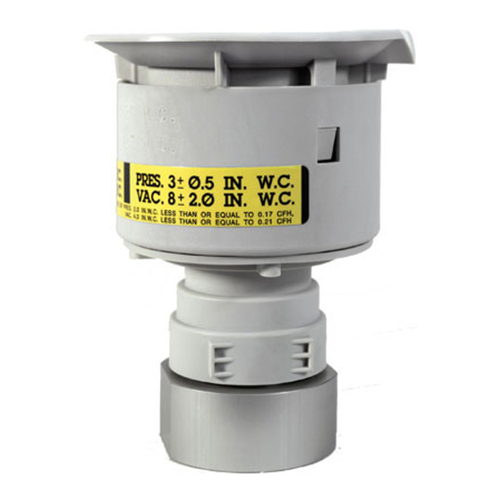
OPW 623V Series Performance Specifications:
This Pressure / Vacuum vent has been manufactured and
tested to the following specifications: Pressure leak rate not
to exceed 0.05 CFH at 2" W.C. Vacuum leak rate not to ex-
ceed 0.21 CFH at -4" W.C. The cracking pressure to be 2.5" to
6" W.C. and cracking vacuum to be -6" to -10" W.C. Tested
using CARB Test Procedure TP-201.1E, TP-201.1E CERT, or
applicable Phase I Executive Order.
Install vent per requirements in NFPA 30. Vents should be
located so that vapors will not be trapped by eaves or other
obstructions.
Torque Specification:
Vent Assembly 2" NPT, 35 ft-lbs minimum to 55 ft-lbs maxi-
mum.
OPW 623V PRESSURE / VACUUM VENT
VALVE INSTALLATION INSTRUCTIONS:
Step 1:
Deburr and thoroughly clean vent pipe.
mounted vertically.
Apply pipe dope to vent pipe threads.
Pipe dope to be a non-hardening, gasoline resistant pipe
thread seal compound.
Step 2: (See Figure 1)
Screw the vent assembly onto the vent pipe and torque to 35
ft.-lbs minimum to 55 ft-lbs maximum. Use the flats on the
NOTE: Vent must be
pipe adaptor only, Do not wrench on the composite valve
assembly.
NOTE: NEVER PAINT OR COVER THE VENT
Figure 1
Operation and Maintenance:
Annual maintenance is required to keep the vent operating
satisfactorily. Remove and inspect filter screens – clean or
replace as necessary. Test as necessary.
Upper Screen Maintenance
1.
Remove vent top by depressing tabs as indicated in Fig.
2, and lift top upward. Screen will slip up and out of
valve.
2.
Clean or replace filter screen (P/N H14895M for 623V)
as necessary and reinstall Fig. 3.
3.
Reinstall vent top by reinserting into the body. Be sure
the tabs are inside the valve body, and then rotate top
until the tabs snap into place.
Figure 2
