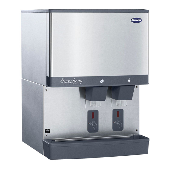
Follett Symphony Plus 50 Series Manuale di installazione - Pagina 8
Sfoglia online o scarica il pdf Manuale di installazione per Fabbricatore di ghiaccio Follett Symphony Plus 50 Series. Follett Symphony Plus 50 Series 17. Ice and water dispensers
Anche per Follett Symphony Plus 50 Series: Manuale (6 pagine)

1. Locate wall bracket mounting position relative
to wall studs (Fig. 8). Install the supplied
wall bracket with six 3/8" diameter fasteners
(Fig. 10.1).
Note: Three holes are available at each fastening
site to allow capture of studs or supports
within the wall.
2. Locate and cut utility hole (Fig. 10.2) in wall
using Fig. 9 dimensions.
3. Rough in utilities. Wall mount bracket
dimensions can be used as a template.
§ Water: 1/2" FNPT
§ Drain: 3/4" MPT
4. Lift dispenser onto wall bracket positioning
unit so that hook on back of dispenser is
captured by wall bracket support angle
(Fig. 10.3).
5. Install two 1/4" X 20 screws through bottom of
wall bracket into bottom of dispenser to secure
dispenser to wall bracket (Fig. 10.4).
6. Install supplied 1/2" MPT X 3/8" push-in
adapter onto 1/2" FNPT water supply.
Fig. 9 – Wall mount, utility location
1.43" (3.6 mm)
3.99" (10.1 cm)
POTABLE WATER
3/8 COPPER TUBE
6.70" (17.0 cm)
POWER CORD EXIT
10.69" (27.1 cm)
3/4 COPPER TUBE
8
25CI425A/W, 25HI425A, 50CI425A/W, 50HI425A
FRONT VIEW
0.77" (2.0 cm)
Fig. 8 – Wall bracket location guide
TOP VIEW
1.00" (25 mm)
2.00" (51 mm)
FRONT VIEW
ANCHOR POINTS
0.438" (11 mm)
CLEARANCE
(406 mm)
12.37" (31.4 cm)
3.44" (8.7 cm)
3.53" (9.0 cm)
Fig. 10 – Wall mount bracket and fastener
requirements
1
2
4
WALL STUDS
WALL STUDS
25HI425A
13" (33.0 cm)
50HI425A
15" (38.1 cm)
16.00"
0.75"
(19 mm)
25HI425A
19" (48.3 cm)
50HI425A
21" (53.3 cm)
6.00"
(15.2 cm)
WALL CUTOUT
3
