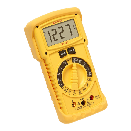
Amprobe HD110C Manuale d'uso - Pagina 6
Sfoglia online o scarica il pdf Manuale d'uso per Multimetro Amprobe HD110C. Amprobe HD110C 14.

DC & AC Voltage Measurement (See Figure 1)
1.
Connect test leads to the meter as shown in Figure 1.
2.
Turn function selector switch to V and the desired range.
3.
Press the AC/DC menu button to display either ac or dc indicator.
4.
Touch Probe tips across voltage source (in parallel with circuit).
5.
Voltage value will appear on Digital Display along with the voltage polarity (for dc).
DC and AC Current Measurement (See Figure 2)
1.
Connect red test lead to the A input for current measurements up to 2 A. Connect black test
lead to COM input connector.
2.
Set the Function Switch to the desired current range.
3.
Press the AC/DC menu button to display either AC or DC indicator.
4.
Open circuit in which current is to be measured (voltage between this point and ground must
not exceed 1000 V ac/1500 V dc). Securely connect test leads in series with the load.
5.
Turn on power to circuit being tested.
6.
Read current value on Digital Display.
Incorrect Input Warning: A tone will sound when a test lead is connected to the amperage jack, but the
selector switch is not set to the correct current range. Ranges 200 µA to 2 A require the test lead to be in
the A jack.
Resistance Measurement (See Figure 3)
1.
Turn off any power to the resistance to be measured and discharge any capacitors. Any
voltage present during a resistance measurement will cause inaccurate readings.
2.
Connect test leads to the meter as shown in Figure 3.
3.
Set Function/Range Switch to the desired resistance range.
4.
Connect test leads to circuit being measured.
5.
Read resistance value on digital display. Open circuits will be displayed as "1".
Diode and Continuity Test (See Figure 4)
The diode test measures the voltage drop across a diode junction.
1.
Connect the test leads as shown in Figure 4.
2.
Set the Function/range switch to � �.
3.
Apply probe tip of red lead to the anode and the black lead to the cathode of the diode.
4.
The meter's display indicates the forward voltage drop (approx. 0.6 V for silicon diode or
0.4 V for germanium diode). An open diode is indicated by "1".
5.
Reverse test lead connections to the diode to perform a reverse bias test. "1" indicates a
good diode.
Notes: "1" for both reverse and forward bias tests indicates an open diode. A low voltage reading for
both bias tests indicates a shorted diode. If the diode is shunted by a resistor of 1000 Ω or less, it must be
removed from the circuit before taking the measurement. Bipolar transistor junctions may be tested in
the same manner described above as emitter-base and base-collector junctions are diode junctions.
When measuring continuity (also for shorted diodes) the meter emits a continuous tone when the
resistance value falls below 50 �.
4
