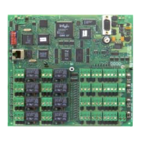
Cardax FT Controller 3000 Nota di installazione - Pagina 6
Sfoglia online o scarica il pdf Nota di installazione per Controllore Cardax FT Controller 3000. Cardax FT Controller 3000 11.

Procedure
1.
2.
3.
4.
Dial-up/Serial setup details
Refer to the Dial-up/Null-Modem Initialisation section of Chapter 23 in the Cardax FT
Command Centre User Guide, for the procedure.
Optical tamper detectors
The front optical tamper detector will sense when the Cabinet door is opened.
The rear optical tamper detector will sense if the Cabinet is removed from its mounting
position.
When the Cardax FT Controller 3000 is re-powered after servicing and is operating correctly
it will initialise the optical tamper detectors.
The following procedure will ensure that the optical tamper sensors are initialised correctly on
power-up.
1.
2.
6
Check the power and Ethernet cabling to the Cardax FT Controller 3000 are correctly
installed.
Locate DIP switch 2 (SW2) on the Cardax FT Controller PCB.
Set switch 2 to ON (closed).
Switch on power to the Cardax FT Controller 3000. The red LED (D1) flashes in the
following sequence:
(The sequence completes fairly quickly but it is important you ensure the LED finishes
indicating the "normal running" sequence.)
-
The red LED flashes fairly fast during startup.
-
The red LED flashes three times per second. The Cardax FT Controller 3000
is waiting for its IP address.
-
When the Cardax FT Controller 3000 has received its IP number, the red LED
flashes twice per second. This indicates the Cardax FT Controller 3000 is
waiting for database information to be downloaded from the Server.
-
When initialisation is complete, the LED flashes approximately once per second
indicating a normal running sequence.
Note: The section titled "Run LED" (later in this chapter) details the different meanings
of the various flash sequences.
Set switch 2 to OFF (open).
Switch on the 13.6 V DC ± 15% supply to the Cardax FT Controller PCB.
Close and lock the Cardax FT Controller cabinet door within three seconds, (i.e. before
the Controller goes into a three flash or normal running state).
Note: The Cabinet door must remain closed for at least 5 seconds for the initialisation of
the optical tamper detectors to be completed.
Part number 3E1089 R3
March 2003
