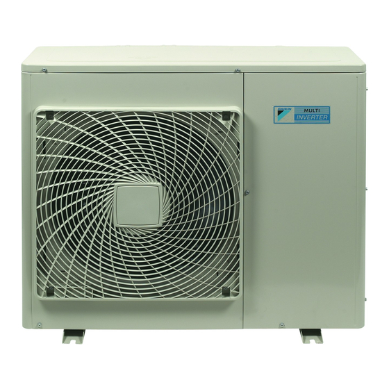
Daikin 4MXS80E3V3B2 Manuale di installazione - Pagina 6
Sfoglia online o scarica il pdf Manuale di installazione per Condizionatore d'aria Daikin 4MXS80E3V3B2. Daikin 4MXS80E3V3B2 16.

9
In coastal areas or other places with salty atmosphere of sulfate
gas, corrosion may shorten the life of the air conditioner.
10 Since drain flows out of the outdoor unit, do not place anything
under the unit which must be kept away from moisture.
Units cannot be installed hanging from ceiling or
NOTE
stacked.
CAUTION
When operating the air conditioner in a low outdoor
ambient temperature, be sure to follow the instructions
described below.
To prevent exposure to wind, install the outdoor unit
with its suction side facing the wall.
Never install the outdoor unit at a site where the
suction side may be exposed directly to wind.
To prevent exposure to wind, install a baffle plate on
the air discharge side of the outdoor unit.
In heavy snowfall areas, select an installation site
where the snow will not affect the unit.
Indoor/outdoor unit installation drawings
(See figure 1)
For installation of the indoor units, refer to the installation manual
which is provided with the units. The diagram shows a wall-mounted
indoor unit.
CAUTION
Do not connect the embedded branch piping to
outdoor unit when only carrying out piping work
without connecting the indoor unit (in order to add
another indoor unit later).
Make sure no dirt or moisture gets into either side of
the embedded branch piping.
See
"Refrigerant piping work" on page 6
It is not allowed to connect 1 indoor unit only.
Be sure to connect at least 2 indoor units. Note
that if a built-in indoor unit is connected, at least
3 indoor units must be connected.
1
Caulk pipe hole gap with putty.
Cut thermal insulation pipe to an appropriate length and wrap it
2
with tape, making sure that no gap is left in the insulation pipe's
cut line.
3
Wrap the insulation pipe with finishing tape from bottom to top.
4
Allow 30 cm of work space below the ceiling surface.
5
25 cm from wall. Allow space for piping and electrical servicing.
If there is danger of the unit falling or overturning, fix the unit with
6
foundation bolts, or with wire or other means.
7
Connection of the outdoor unit
8
Service cover
Installation manual
3
Construct a large canopy.
Construct a pedestal.
Install the unit high enough off the
ground to prevent burying in snow.
for details.
If the location does not have good drainage, place the unit on a
level mounting base (or a plastic pedestal). Install the outdoor
unit in a level position. Failure to do so may result in water
leakage or accumulation.
Also insulate the connection on the outdoor unit.
1
Insulation tape
2
Clamping material
3
Insulation tube
4
Service lid
Use tape or insulating material on all connections to prevent air
from getting in between the copper piping and the insulation
tube. Be sure to do this if the outdoor unit is installed as shown
in the figure.
Installation
Install the unit horizontally.
The unit may be installed directly on a concrete verandah or a
solid place if drainage is good.
If the vibration may possibly be transmitted to the building, use a
vibration-proof rubber (field supply).
Connections (connection port)
Install the indoor unit according to the table below, which shows the
relationship between the class of indoor unit and the corresponding
port.
The total indoor unit class that can be connected to this unit:
Heat pump type:
4MXS80 - Up to 14.5 kW
5MXS90 - Up to 15.6 kW
Model
A
4MXS80
15
20
25
35
42
5MXS90
15
20
25
35
42
(1) Use no. 2 and 4 reducers to connect pipes.
(2) Use no. 5 and 6 reducers to connect pipes.
(3) Use no. 1 and 3 reducers to connect pipes.
Refer to
"How to use reducers" on page 7
numbers and their shapes.
1
2
3
Port
B
C
D
(1)
(2)
(2)
15
15
15
(1)
(2)
(2)
20
20
20
(1)
(2)
(2)
25
25
25
(1)
(2)
(2)
35
35
35
(1)
(2)
(2)
42
42
42
(3)
(3)
50
50
50
(3)
(3)
60
60
60
71
71
(1)
(2)
15
15
15
(1)
(2)
20
20
20
(1)
(2)
25
25
25
(1)
(2)
35
35
35
(1)
(2)
42
42
42
(3)
50
50
(3)
60
60
71
for information on reducer
4
E
—
(2)
15
(2)
20
(2)
25
(2)
35
(2)
42
(3)
50
(3)
60
71
