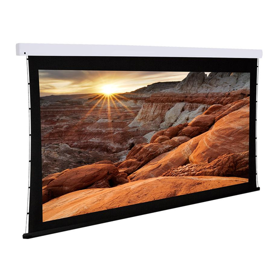
Dragonfly DFM-TAB-110 Manuale di installazione - Pagina 5
Sfoglia online o scarica il pdf Manuale di installazione per Schermo di proiezione Dragonfly DFM-TAB-110. Dragonfly DFM-TAB-110 17. Dfm-tab screens
Anche per Dragonfly DFM-TAB-110: Manuale d'uso (8 pagine)

4. Pre-Installation
Before installing the projection screen, review this section thoroughly to be sure that no additional work is needed
to prepare the job for mounting and controlling the screen.
4.1. Required for Installation
Have an assistant help with installation to prevent damage or injury. The following tools will be needed to complete
the installation:
•
Phillips Screwdriver
•
2 Step Ladders
•
Electric or Cordless Drill
•
Marker
4.2. Unpacking the Projection Screen
As you unpack the projection screen:
•
Remove all accessories from the box before
discarding any packaging. Use the Package Contents
section to verify that everything has been removed.
•
After the screen is out of the packaging, remove
the tape holding the bottom rail of the screen in the
housing.
•
Do not remove the black bands from the ends of the
projector until it has been mounted. These bands
keep the bottom bar from falling into the housing and
getting stuck.
•
While unpacking and preparing the projection screen for installation, take note of the location of the adjustment
screws and grommet. It may be difficult to locate them after the screen is hanging from the mounting brackets.
•
Do not turn the adjustment screws until the screen is mounted and ready to be adjusted.
4.3. Powering the Screen
Operating Voltage:
110 Volts AC
Amperage:
.96 Amps
The screen has a five foot power cable permanently attached to the left side of the screen as seen from the
viewing area. Install or locate a receptacle close enough to plug the screen in prior to installation.
4.4. Mounting Considerations
The design of the brackets allows for wall, ceiling, or hanging mounting. Plan the final height of the screen's
viewing surface prior to installation. Make sure there is enough room for the screen to hang freely below the
mounting location when extended.
Warning! The building structure and material in the mounting location must be capable of safely supporting
the weight of the projection screen. Included hardware is only meant for use with wood, surfaces with
wood bracing behind them, or concrete surfaces. Confirm with an engineer or contractor that the building
material will safely support the weight of the screen using the included mounting hardware.
4.5. Control Method
Dragonfly motorized screens can be controlled via manual wall switch, IR remote, 12 volt trigger, or RS232.
Complete instructions for each method are described in the Control Setup section (Page 8). Decide on the method
that will be used before installation begins. Pre-wire any cables from projectors or control systems prior to closing
the walls or ceiling.
www.snapav.com Support: 866.838.5052
•
Level
•
7/32" Masonry Drill Bit to install 8mm concrete anchors
•
5/32" Drill Bit to install 6mm Wall Switch Screw anchors (optional)
Remove (2) Screws Holding Bar in Place
(Back of Housing)
Remove
Tape
Adjustment Screw
Grommet Location
DFM-TAB Installation Manual
Adjustment
Screws
Viewing
Area
Pg. 5
