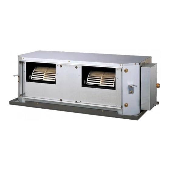
AirStage ARUH60RLAV Manuale di installazione - Pagina 8
Sfoglia online o scarica il pdf Manuale di installazione per Condizionatore d'aria AirStage ARUH60RLAV. AirStage ARUH60RLAV 15. Indoor unit (duct type)

] 1
6.1. Electrical requirement
Voltage rating
Operating range
• Select the power cable type and size in accordance with relevant local and national
regulations.
• Specifi cations for local wiring power cord and branch wiring are in compliance with local code.
• Select the correct cable type and size according to the country or region's regulations.
• Max. wire length: Set a length so that the voltage drop is less than 2%. Increase the
wire diameter when the wire length is long.
Refer to the table for the breaker specifi cations of each installation condition.
Perform the power crossover wiring within the range of the same refrigerant system. When
the crossover wiring is done, make a connection for indoor unit to satisfy conditions A and
B below.
A. Current breaker requirements
Model
ARUH36RLAV
ARUH48RLAV
ARUH60RLAV
MCA: Minimum Circuit Ampacity
MOP: Maximum Overcurrent Protection
When the power crossover wiring is done, make it so that the total of the MCA of the con-
nected indoor equipment does not exceed the 15 A.
B. Earth leakage breaker requirements
Breaker capacity
30 mA, 0.1 sec or less
100 mA, 0.1 sec or less
200 mA, 0.1 sec or less
If the number of units of connected indoor unit exceeds the upper limit, either add breakers
or use a breaker with large capacitance.
6.1.1. Transmission and remote controller wiring specifi cations
Follow the specifi cations below for the transmission and remote controller cable.
Cable size
22 AWG
Transmission cable
(0.33 mm²)
22 AWG
Remote controller cable
(0.33 mm²)
En-7
208/230 V
187 to 253 V
MCA
MOP (Fuse capacity)
2.59 A
3.93 A
20 A
4.29 A
Maximum connectable indoor unit
8
27
39 (Upper limit of the refrigerant system)
Wire type
LEVEL 4 (NEMA) non-
polar 2core, twisted
LONWORKS ®
pair solid core diam-
compatible cable
eter 1/32 in. (0.65mm)
Sheathed PVC cable
] 1
6.2. Wiring method
(EXAMPLE)
Power supply
Outdoor unit
Transmission
Transmission
Power
supply
Breaker 2
Breaker 1
Power supply
(Crossover wiring of power supply)
Power
supply
Pull box
Remarks
Breaker
Breaker 1
Polar 3 core
Power supply
Twisted pair
1
6.3. Unit wiring
Before attaching the cable to terminal block.
6.3.1. Power supply cable
Adjust the length of power supply cable to avoid excessive tension with referring fi gure below.
For U.S.A. and Canada
For Others
Breaker 1 : Earth leakage breaker
Breaker 1
Breaker 2 : Current breaker
Breaker 2
Power supply
Indoor unit
Indoor unit
Transmission
Power
Remote
supply
Remote
control
control
Breaker 2
Breaker 1
Remote
controller
(Master)
Power supply
Indoor unit
Power
Remote
supply
control
2
Pull box
Remote
controller
(Master)
31/32 in.
2-5/32 in.
(25 mm)
(55mm)
Earth (Ground)
31/32 in.
2-9/16 in.
wire
(25 mm)
(65mm)
25/32 in. (20 mm)
1-3/16 in. (30 mm)
Earth
(Ground) wire
(GFCI breaker)
(MOP breaker)
Indoor unit
Transmission
Power
supply
Remote
control
Breaker 2
Breaker 1
Remote
Remote
controller
controller
(Slave)
Power supply
Indoor unit
Indoor unit
Power
Remote
supply
Remote
control
control
Remote
Remote
controller
controller
(Slave)
Conduit connector
