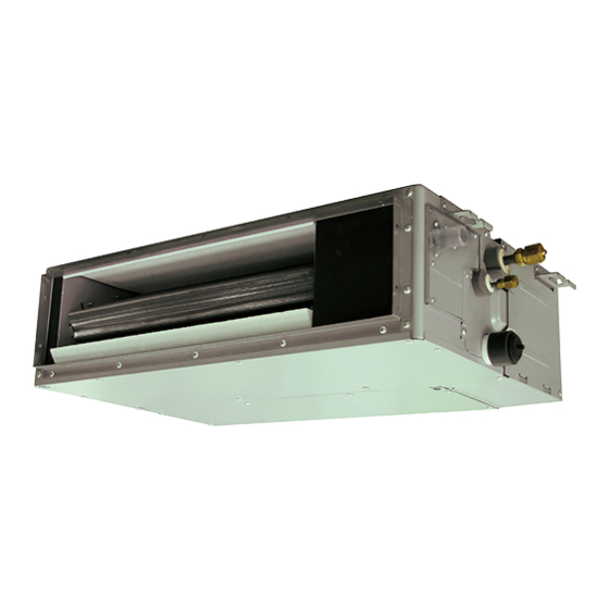
AirStage ARXD009GLEH Manuale di installazione - Pagina 16
Sfoglia online o scarica il pdf Manuale di installazione per Condizionatore d'aria AirStage ARXD009GLEH. AirStage ARXD009GLEH 18. Indoor unit (duct type)

7. FIELD SETTING
There are 3 methods for address setting by FIELD SETTING as follows.
Set by either of the methods.
Each setting method is described (1) to (3) below.
(1) IU AD, REF AD SW settings ...... This section (7.1. Setting the address)
(2) Remote controller settings ......... Refer to the wired or wireless remote controller
(3) Automatic address settings ....... Refer to the outdoor unit manual for detailed setting
Be sure to turn OFF the power before performing the fi eld setting.
7.1. Setting the address
Manual address setting method
• If the receiver unit is attached, the indoor unit address and the refrigerant circuit
address can also be set up through the wireless remote controller.
Use an insulated screwdriver to set the DIP switches.
For indoor
unit address
×10
Setting
Setting
range
Indoor unit address
0 to 63
Refrigerant circuit
0 to 99
address
7.1.1. Indoor unit address
Rotary switch (IU AD × 1)...Factory setting "0"
Rotary switch (IU AD × 10)...Factory setting "0"
When connecting multiple indoor units to 1 refrigerant system, set the address at IU
AD SW as shown in the Table A.
7.1.2. Refrigerant circuit address
Rotary switch (REF AD × 1)...Factory setting "0"
Rotary switch (REF AD × 10)...Factory setting "0"
In the case of multiple refrigerant systems, set REF AD SW as shown in the Table A
for each refrigerant system.
Set to the same refrigerant circuit address as the outdoor unit.
• If working in an environ-
Table A
ment where the wireless
remote controller can be
Address
used, the addresses can
also be set using the
Refrigerant
remote controller.
circuit
• If setting the addresses
using the wireless
remote controller, set
the indoor unit address
and refrigerant circuit
address to "00".
(For information on set-
ting using the wireless
remote controller.)
* Do not set the indoor
10
unit address (IU AD
SW) at 64 to 99.
11
It may result in failure.
99
En-15
manual for detailed setting information. (Set IU AD,
REF AD SW to 0)
information. (Set IU AD, REF AD SW to 0)
CAUTION
CAUTION
For refrigerant
circuit address
IU AD
REF AD
RC AD
×1
×10
×1
SET3
SET4
Type of switch
Setting
example
2
IU AD × 10
Setting
example
63
REF AD × 10
Rotary switch
Address
setting
REF AD SW
Indoor unit
× 10
× 1
0
0
0
0
1
0
1
1
2
0
2
2
3
0
3
3
4
0
4
4
5
0
5
5
⁞
⁞
⁞
⁞
1
0
10
1
1
11
⁞
⁞
⁞
⁞
9
9
63
7.2. Custom code setting
Selecting the custom code prevents the indoor unit mix-up.
(Up to 4 codes can be set.)
Perform the setting for both the indoor unit and the remote controller.
Indoor
unit
Remote
controller
Custom code setting for indoor unit
Set the DIP switch SET 3 SW1, SW2 referring to the Table B.
OFF
Table B
DIP switch SET3 SW1
DIP switch SET3 SW2
7.3. Static pressure mode
If the applicable static pressure does not match the static pressure mode, the static
pressure mode may be changed to another mode manually.
It is necessary to set up a static pressure mode for each usage of static pressure.
Static pressure can be set at site.
Relation between set values and static pressure are as the following table.
• FUNCTION SETTING can be performed with the wired or wireless remote controller.
(The remote controller is optional equipment)
IU AD × 1
• Refer to the wired or wireless remote controller manual for detailed setting information.
Function
Number
00
01
REF AD × 1
02
03
04
05
26
06
07
08
09
31
* Please refer to FAN PERFORMANCE CURVE within Design & Technical Data for the
features of each setting.
Rotary switch
setting
7.4. Switching of drainage function
IU AD SW
× 10
× 1
If contained drain pump is not used, set the drainage function to "Invalid" in the drainage
0
0
function switching.
• If contained drain pump is not use:
0
1
When used under "WALL MOUNTED TYPE/FLOOR STANDING CONCEALED
0
2
TYPE".
0
3
When used in natural drainage under "CEILING CONCEALED TYPE".
• Installation method
0
4
Set the DIP switch SET 4 SW1, SW1 referring to the Table C.
0
5
⁞
⁞
1
0
1
1
OFF
⁞
⁞
6
3
Table C
DIP switch
SET 4 SW1
Confusion
Dip switch "SET 3"
IU AD
ON
×10
A (Factory setting)
OFF
OFF
CAUTION
Setting Number
AR004 AR007 AR009 AR012 AR014 AR018 AR024
SP mode 00
SP mode 01
SP mode 02
SP mode 03
SP mode 04
SP mode 05
SP mode 06
SP mode 07
SP mode 08
SP mode 09
SP mode 31
(Factory setting)
Dip switch "SET 4"
IU AD
ON
×10
OFF
Drainage function "Valid" (Factory setting)
ON
Drainage function "Invalid"
Code change
A
B
C
D
A
B
C
D
REF AD
RC AD
×1
×10
×1
SET3
SET4
Custom code
B
C
D
ON
OFF
ON
OFF
ON
ON
Setting Static Pressure
0 Pa
10 Pa
20 Pa
30 Pa
40 Pa
50 Pa
60 Pa
70 Pa
(50
Pa)
80 Pa
90 Pa
25 Pa
REF AD
RC AD
×1
×10
×1
SET3
SET4
