DRAKE ENCODER HOST EH244 Manuale di istruzioni - Pagina 6
Sfoglia online o scarica il pdf Manuale di istruzioni per Convertitore multimediale DRAKE ENCODER HOST EH244. DRAKE ENCODER HOST EH244 11. Encoder host
Anche per DRAKE ENCODER HOST EH244: Manuale di istruzioni (20 pagine)

6
Configuration
The EH244 is configured by either the front-panel in-
terface or the ethernet-connected web server inter-
face. When the unit is first installed, the front-panel
should be used to configure the unit's IP settings be-
fore using the ethernet controls; most configuration
of the unit may be performed from the front panel if
the operator chooses to do so.
Front Panel Configuration
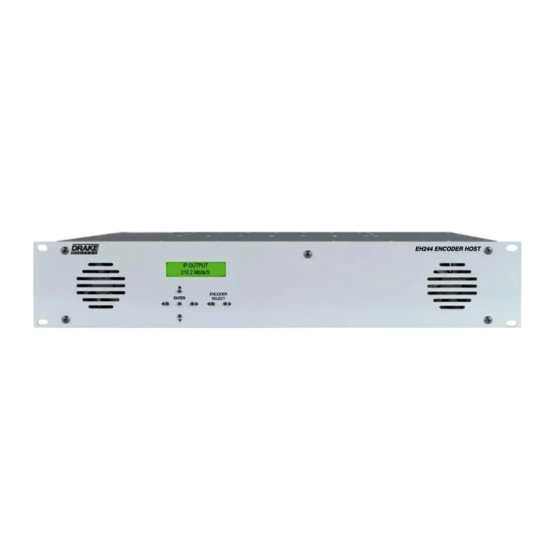
The front panel can display several useful status
messages that can be selected by using the but-
tons to the right of the LCD. When pressing the but-
ton above the ENTER button, the LCD display will
cycle between: the currently-installed firmware ver-
sion; the IP address currently assigned to the eth-
ernet control interface; and the MAC address of the
ethernet control interface. When pressing the button
below the ENTER button, the LCD display will cycle
between the output channel bit-rates of the 4 outputs.
To use the front panel to change settings, press one
of the two buttons labeled ENCODER SELECT until
the LCD display says EH244, and then hold in the
center button labeled ENTER for about two seconds
(until the LCD display begins to blink). At this point,
you are in configuration mode, and you can use the
two buttons on either side of the ENTER button to
switch between settings on the unit; pressing the
buttons above or below the ENTER button will cycle
through the valid values for the setting currently dis-
played on the LCD. When all configuration is com-
plete, pressing the ENTER button again will save all
settings and return the front panel to its normal mode.
The following settings are available from the front
panel:
· USER NAME: Variable – this sets the username
for the ethernet control interface authorization; this
field is case-sensitive
· PASSWORD: Variable – this sets the password
for the ethernet control interface authorization; this
field is case-sensitive
· HOST NAME: Variable – this sets the display
hostname for the ethernet control interface
· DHCP: ENABLED, DISABLED – this configures the
ethernet control interface to use DHCP for its IP con-
figuration settings when enabled, or to use the static
IP configuration that follows when disabled
· IP ADDRESS: Variable – this sets the ethernet
control interface's static IP address when DHCP is
disabled
· SUBNET MASK: Variable – this sets the eth-
CONFIGURATION
ernet control interface's IP subnet netmask when
DHCP is disabled
· GATEWAY ADDRESS: Variable – this sets the
default gateway for the ethernet control interface
when DHCP is disabled
· DTA/EAS
SLAVE – this sets the unit's EAS and DTA control
mode. When Master, the unit is the first in the daisy
chain of Drake devices; when slave, the unit is not
the first in the daisy chain
· DTA MODE: DISABLED, ENABLED – this enables
the DTA control feature of the unit (which allows
SCTE65 control messages to be passed out to
low-cost DTA settop boxes for channel lineup and
firmware update purposes)
· EAS
MODE:
18, MODULE 6+SCTE 18 – this sets the EAS
mode in use. MODULE 6 replaces all video and audio
streams with the input from the EAS encoder when
an EAS alert is active. SCTE 18 sends the SCTE 18
EAS control messages when an EAS alert is active.
MODULE 6+SCTE 18 performs both actions when
an EAS alert is active
· EAS RF CHANNEL: Channel number – this con-
figures the SCTE 18 force-tuning RF channel num-
ber that every receiver should tune to during an EAS
alert
· EAS MODULATION: QAM-64B, QAM-256B – this
configures the SCTE 18 force-tuning channel modu-
lation method that every receiver should tune to dur-
ing an EAS alert
· EAS MPEG PROG #: Program number – this
configures the SCTE 18 force-tuning MPEG program
number that every receiver should tune to during an
EAS alert
· EAS MAJOR CHAN: Major number – this sets
the PSIP major channel number of the SCTE 18
force-tuning channel
· EAS MINOR CHAN: Minor number – this sets
the PSIP minor channel number of the SCTE 18
force-tuning channel
· PACKET DELAY: 0-200 usec – this sets the de-
lay interval between encoder output packets, in mi-
croseconds. This setting may be used to enable
older settop boxes with small decoder buffers to work
with the SDE24 encoder's output stream. If needed,
a setting around 70-100usec works well, but this set-
ting must be tweaked for each encoder based on the
deployed settop boxes
· OUTPUTx BITRATE: Variable – when a specific
output is not being used for generating a QAM chan-
nel, the output bitrate may be varied to allow for more
CONTROL:
DISABLED, MASTER,
DISABLED, MODULE 6, SCTE
