DRAKE DQT1000 Manuale di istruzioni - Pagina 7
Sfoglia online o scarica il pdf Manuale di istruzioni per Modulatore DRAKE DQT1000. DRAKE DQT1000 15. Digital to qam transcoder; multiplexing qam modulator

R1
R2
RF OUTPUT
EAS IN
DQT1000 - shown above
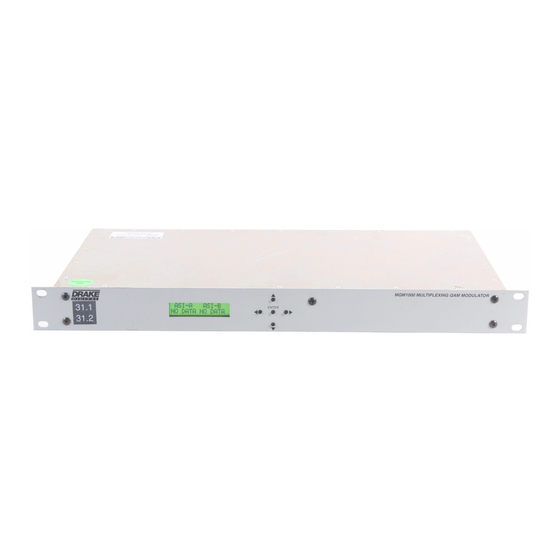
MQM1000 - same as DQT1000 except that the MQM1000
does not have the R3 and R4 demodulator inputs or the
ASI optional input. Instead it has two standard ASI inputs
in place of the RF inputs on the DQT1000. The ASI inputs
are type BNC female connectors. These inputs are used
to input the ATSC transport streams in ASI format instead
of RF.
R
1, RF OUTPUT – This is the high level (61 dBmV), 54 to
1002 MHz, output from the DQT1000 upconverter section.
R2, EAS IN – This input may be used to input an alternate
program, usually for emergency alert system requirements.
This is a 44 MHz IF input and the operating level is
+30 dBmV. An auto sensing switch is built in and will
switch the IF to this input whenever the RF level at this jack
exceeds approximately +20 dBmV at 44 MHz. The input
signal can be either analog or digital. When this input is
activated, the demodulators and ASI inputs are essentially
switched off as the output will be determined by the IF
signal input through this jack.
R3, DEMOD A IN - DQT only - 54 to 864 MHz input for
DEMOD A. From an off-air antenna or CATV system.
R3, ASI INPUT A - MQM only.
R4, DEMOD B IN - DQT ONLY - 54 to 864 MHz input for
DEMOD B, if installed. From an off-air antenna or CATV
system.
R4, ASI INPUT B - MQM only.
R5, ASI INPUT - DQT only - Optional DVB ASI format
MPEG2 transport stream input. If installed, an ATSC
stream from this input may be multiplexed with the stream
from DEMOD A.
,
Rear Panel Connections
R3
DEMOD A
IN
R4
R5
DEMOD B
IN
ASI INPUT
R6, FAN – This cooling fan pulls air through the unit for
cooling. If this fan fails or is blocked the unit may become
warm enough to cause the OVER TEMP alert to be
activated. If the fan has failed, it should be replaced as
soon as possible. Operation with an over temperature
condition present for an extended period of time will lead
to premature component failure even though the unit may
be functioning normally when the condition is first noted.
R7, RS232 IN - Connection to a PC or modem for use with
remote control / monitoring program or for firmload
download.
R8, RS232 OUT - Loop to another DQT or MQM.
R9, AC Line Cord – For connection to the nominal
120 VAC power source. This unit is designed for use in
countries with 120 VAC power standards but the power
supply will accept an input voltage range of 90 VAC
minimum to 260 VAC maximum with a power line
frequency of either 50 or 60 Hz.
7
R6
R7
R9
RS232 IN
AC POWER
120 VAC 60 Hz
30 WATTS
RS232 OUT
R8
