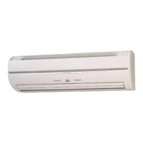
AirStage ASUA12TLAV Manuale di installazione - Pagina 14
Sfoglia online o scarica il pdf Manuale di installazione per Condizionatore d'aria AirStage ASUA12TLAV. AirStage ASUA12TLAV 15. Indoor unit (wall mounted type)

L1, L2 (N):
Power supply
cable
Power supply
earth (ground)
cable
Earth (ground)
terminal for wired
remote controller
(if necessary)
Do not route the cables over the screw hole.
GOOD
Cable
Screw hole
When you attach the cable clamp, make sure that the cables are not jutting out from the
clamp or being pinched by the clamp.
(2) Install the cable clamp and piping cover.
Piping cover
En-13
X1, X2:
Transmission
cable
PROHIBITED
Cable
Screw hole
Piping cover
Screw
Cable clamp
Screw
Screw
7. FINISHING
After checking for gas leaks (refer to the Installation Manual of the outdoor unit),
perform this section.
Install heat insulation around both the large (gas) and small (liquid) pipes. Failure to
do so may cause water leaks.
(1) Insulate between pipes.
• For rear, right, and bottom piping, overlap the connection pipe heat insulation and
indoor unit pipe heat insulation and bind them with vinyl tape so that there is no
gap.
• For left and left rear piping, butt the connection pipe heat insulation and indoor unit
pipe heat insulation together and bind them with and vinyl tape so that there is no
gap.
Connection pipe
(Heat insulation)
Bind the pipes together so that
there is no gap.
Seal A is used when the diameter
of gas pipe is 1/2 inch or more.
Butt connection pipe (heat insulation) against the indoor unit pipe
(heat insulation) and wrap with seal A so that there is no gap.
• For left and left rear piping, wrap the area which accommodates the rear piping
housing section with cloth tape.
Pipe
Drain hose
• For left and left rear piping, bind the connection cable to the top of the pipe with
vinyl tape.
• For left and left rear piping, bundle the piping and drain hose together by wrapping
them with cloth tape over the range within which they fi t into the rear piping
housing section.
(2) Temporarily fasten the connection cable along the connection pipe with vinyl tape.
(Wrap to about 1/3 the width of the tape from the bottom of the pipe so that water
does not enter.)
Connection cable –
Wall pipe
Drain hose
(3) Fasten the connection pipe to the outside wall with saddles, etc.
Saddle*
Pipe
(4) Fill the gap between the outside wall pipe hole and the pipe with sealer so that rain
water and wind cannot blow in.
(5) Install the front panel.
• First, fi t the lower part of the front panel, and insert top and bottom hooks. (3 top
sides, 6 bottom sides)
CAUTION
Overlap the insulation
Indoor unit pipe
(Heat insulation)
Vinyl tape
Wrap with cloth tape
Cloth tape
Power supply cable
Transmission cable
Connection pipe
Outside wall cap*
Sealer putty*
Wall
(Outdoors)
*Field supply
