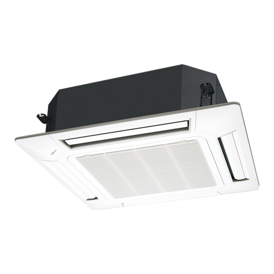
AirStage AUUB24TLAV Manuale di installazione - Pagina 3
Sfoglia online o scarica il pdf Manuale di installazione per Condizionatore d'aria AirStage AUUB24TLAV. AirStage AUUB24TLAV 17. Indoor unit (cassette type)

2. ABOUT THIS PRODUCT
2.1. Precautions for using the R410A refrigerant
WARNING
Do not introduce any substance other than the prescribed refrigerant into the
refrigeration cycle.
If air enters the refrigeration cycle, the pressure in the refrigeration cycle will become
abnormally high and cause the piping to rupture.
If there is a refrigerant leakage, make sure that it does not exceed the concentration
limit.
If a refrigerant leakage exceeds the concentration limit, it can lead to accidents such
as oxygen starvation.
Do not touch refrigerant that has leaked from the refrigerant pipe connections or other
area. Touching the refrigerant directly can cause frostbite.
If a refrigerant leakage occurs during operation, immediately vacate the premises and
thoroughly ventilate the area.
If the refrigerant comes in contact with a fl ame, it produces a toxic gas.
2.2. Special tool for R410A
WARNING
To install a unit that uses the R410A refrigerant, use dedicated tools and piping
materials that have been manufactured specifi cally for R410A use.
Because the pressure of the R410A refrigerant is approximately 1.6 times higher
than the R22, failure to use dedicated piping material or improper installation can
cause rupture or injury.
Furthermore, it can cause serious accidents such as water leakage, electric shock,
or fi re.
Tool name
Pressure is huge and cannot be measured with a conventional
(R22) gauge. To prevent erroneous mixing of other refrigerants,
the diameter of each port has been changed.
Gauge manifold
It is recommended to use a gauge manifold with a high pressure
display range 30 in.Hg to 768 psi (–0.1 to 5.3 MPa) and a low
pressure display range 30 in.Hg to 551 psi (–0.1 to 3.8 MPa).
To increase pressure resistance, the hose material and base
Charging hose
size were changed.
A conventional (R22) vacuum pump can be used by installing
a vacuum pump adapter. Be sure that the pump oil does not
Vacuum pump
backflow into the system. Use one capable for vacuum suction
of 5 Torr, –755 mm Hg (–100.7 kPa).
Gas leakage
Special gas leakage detector for HFC refrigerant R410A.
detector
2.3. Accessories
WARNING
For installation purposes, be sure to use the parts supplied by the manufacturer or
other prescribed parts.
The use of non-prescribed parts can cause serious accidents such as the unit to fall,
water leakage, electric shock, or fi re.
The following installation parts are furnished. Use them as required.
Keep the Installation Manual in a safe place and do not discard any other
accessories until the installation work has been completed.
Name and Shape
Operation Manual
Installation Manual
Cable tie (Large)
Cable tie (Medium)
Contents of change
Q'ty
Application
1
(This book)
1
For fi xing the connection
pipe (Large and Small)
4
For transmission and remote
2
controller cable binding.
Coupler heat insulation
(Small)
Coupler heat insulation
(Large)
Template (Carton top)
Washer
Drain hose insulation
Drain Hose
Hose Band
Drain Pipe Insulation
2.4. Optional parts
Description
Model
UTY-XWZXZC
UTY-XWZXZB
External connect kit
UTY-XWZXZD
UTY-XWZXZ7
UTY-XWZXZE
2.5. About unit of the length
All Fujitsu General products are manufactured to metric units and tolerances. United
States customary units are provided for reference only. In cases where exact dimensions
and tolerances are required, always refer to metric units.
3. INSTALLATION WORK
Correct initial installation location is important because it is diffi cult to move unit after it is
installed.
3.1. Selecting an installation location
WARNING
Select installation locations that can properly support the weight of the indoor. Install
the units securely so that they do not topple or fall.
Do not install the unit in the following areas:
• Area with high salt content, such as at the seaside.
It will deteriorate metal parts, causing the parts to fail or the unit to leak water.
• Area fi lled with mineral oil or containing a large amount of splashed oil or steam,
such as a kitchen.
It will deteriorate plastic parts, causing the parts to fail or the unit to leak water.
• Area that generates substances that adversely affect the equipment, such as sulfuric
gas, chlorine gas, acid, or alkali.
It will cause the copper pipes and brazed joints to corrode, which can cause
refrigerant leakage.
• Area that can cause combustible gas to leak, contains suspended carbon fi bers or
fl ammable dust, or volatile infl ammables such as paint thinner or gasoline.
If gas leaks and settles around the unit, it can cause a fi re.
• Area where animals may urinate on the unit or ammonia may be generated.
For indoor side pipe joint (Small)
1
For indoor side pipe joint (Large)
1
For installing indoor unit.
1
For installing indoor unit.
8
For installing drain hose
1
For installing drain pipe
(Ø 3/4 in. [I.D.]; Ø 1-1/16 in. [O.D.])
1
For installing drain hose
1
For installing drain pipe
1
Application
For output function
(Output terminal / CNB01)
For control input function
(Apply voltage terminal / CNA01)
For control input function
(Dry contact terminal / CNA02)
For forced thermostat off function
(Apply voltage terminal / CNA03)
For forced thermostat off function
(Dry contact terminal / CNA04)
CAUTION
En-2
