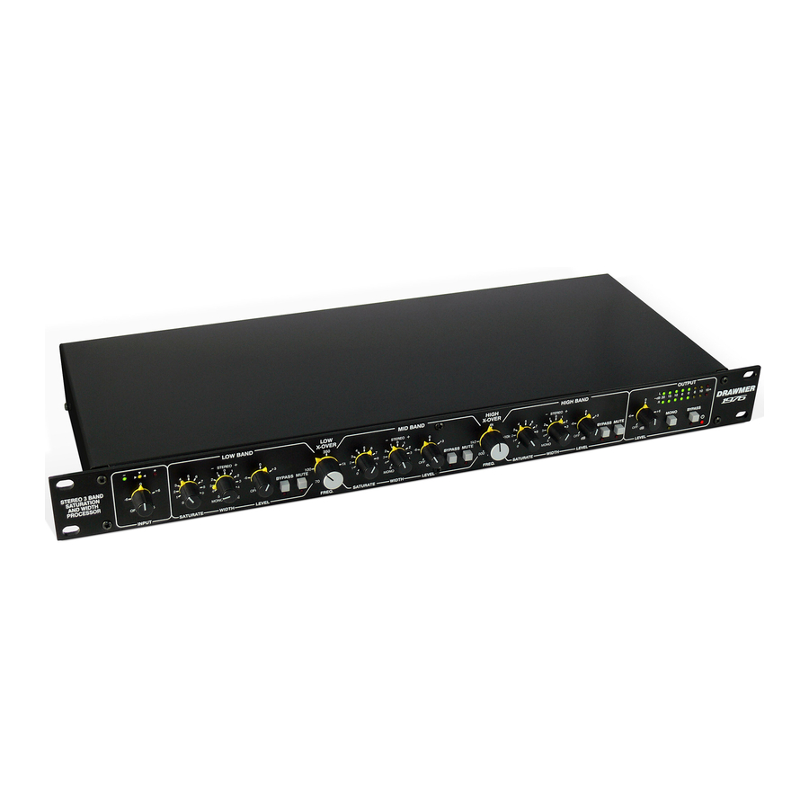
Drawmer 1976 Manuale dell'operatore - Pagina 7
Sfoglia online o scarica il pdf Manuale dell'operatore per Hardware del computer Drawmer 1976. Drawmer 1976 13. Stereo 3 band saturation and width processor

3
LOW, MID & HIGH SATURATION & WIDTH
BANDS
The controls for the Low, Mid and High Bands are identical
and only differ in the frequency range that they operate
within, as set by the x-over frequencies
(3a)
SATURATE:
Sets the amount of drive that the saturation circuitry creates,
from none (0) through subtle and to extreme (10), adding
harmonic distortion within that band as it is rotated
clockwise, and warming the recording.
(3b)
WIDTH:
In order to increase/decrease the stereo width and
spaciousness of each band the 1976 manipulates the left and right phases of the stereo signal so that one side is
in/out of phase with the other. Using the control the width of the stereo image of each band can be made narrower
(-5 mono) or wider (+5 wide) than the width that the incoming signal supplies. At the 0 position the width is not
affected (i.e. the Left and Right phase is unaltered) and is the same as that in the input.
You'll notice that the nearer the mono end of the control the volume level of the band increases and when wider the
level decreases, and this must be taken into account when adjusting the Level control
balance within the recording.
(3c)
LEVEL:
(3a)
As the Saturation
is needed to offset these changes so that the overall level balance for low, mid and high within the recording is
maintained.
(3d)
BYPASS:
In the OFF position all the controls of that particular band are in operation and saturation and width takes place. In
the ON position the signal for the low, mid, or high band is allowed to pass through to the summing stage without
being altered by the saturation stage (including width and gain).
(3e)
MUTE:
In the ON position the signal for that particular band is effectively turned off (muted) and will not be heard at the
output.
Any combination of bypass and mute is available, for example, to hear only the signal of the low band mute the mid
and high bands etc. Using a combination of mute and bypass switches for the various bands allows the operator to
hear and monitor only the frequencies that are required and so 'tune in' to the low, mid and high frequency settings
using the x-over controls
4
OUTPUT
The individual signals from the three bands are summed back
to a single stereo full band and pass through the output circuitry.
(4a)
LEVEL TRIM:
The 1976 provides a single control to modify the stereo output
level after summing, without having to adjust the three band
gain controls (and thus altering the mix). Adjust so that the
output signal approaches the desired level only on signal peaks.
(4b)
VU METER:
A 16 Led bar meter provides visual monitoring for the left and
right signals.
What is heard at the output is shown on this meter, so, with all
bands in operation the full band stereo signal is shown. However,
using a combination of the mute
any combination of signal.
(4c)
MONO:
If you wish to record in mono treat the left and right channels as separate and use accordingly for both tracks. The
MONO switch in the output section is not used to monogise the signal for recording, as such, but has been
incorporated as a testing feature. Because the 1976 alters the phase between the left and right channels to control
the stereo width, activating the MONO switch
will cancel each other out leaving just the signal that lies in mono. This allows the engineer to hear what signal is
lost should it be played in mono and emphasize when you have 'gone too far' with the width controls
band. These can then be adjusted to preference.
(4d)
BYPASS:
A fully balanced hard-wire unit bypass connects the input directly to the output. When active the VU Meter
show the input levels.
(4e)
POWER LED:
The 1976 is on when the Led is illuminated, as controlled by the power switch on the reverse of the unit.
(2)
.
0 - 10
-5 (MONO) - +5 (WIDE)
OFF - +6
(3b)
and Width
controls have an affect on the volume of that particular band the Level control
ON - OFF
ON - OFF
(2)
.
OFF - +12dB
-20 - +15dB
(3e)
and bypass
ON - OFF
ON - OFF
Illuminted - OFF
DRAWMER 1976 O
(3d)
switches within the bands the meters can be made to show
(4c)
will combine the stereo channels, the phase of the left and right
M
PERATOR'S
ANUA
(3c)
to maintain the band
L
(3b)
of each
(4b)
will
7
