BD Diesel Performance 1037135 Manuale di installazione - Pagina 6
Sfoglia online o scarica il pdf Manuale di installazione per Automobile Accessories BD Diesel Performance 1037135. BD Diesel Performance 1037135 18.

8 February 2021
BD Universal Remote Mount Vacuum Brake
6
Control Valve Assembly
The control valve assembly has two hoses
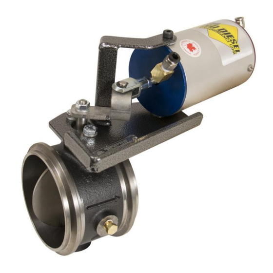
attached to it. Push the shorter piece onto
the barbed fitting on the front cap of the
vacuum cylinder on the exhaust valve
assembly (see Diagram 1) and push the
longer piece onto the barb fitting on the
back cap (Red).
With the hoses now attached, locate or drill
a new hole on the inner frame rail to mount
the control valve assembly within reach of
the hoses.
Existing holes or new holes will have to be drilled out to 5/16". Mount the control valve
assembly to the frame using the long bolt, spacer and nut provided (Dia. 2). A good
ground must be made when bolting bracket to frame rail.
There is a loose section of plastic hose that came included with the spool valve kit
with a yellow plastic vent filter on it. Attach this to the spool valve (#3) and run to a dry
location inside your cab. This vent prevents moisture from entering inside the control
(spool) valve.
NOTE: If the vehicle has a vacuum assisted hydraulic brake booster or the vacuum
pump is located on the driver side, then run the hose and wire along a cross member
and up the driver's side frame rail.
In the engine compartment, locate the hose coming from the vacuum pump on the
engine or to the vacuum assisted hydraulic Brake Booster. (On newer Chevrolets,
the Air Conditioner Pump will have to be unbolted from its bracket and pushed off to
one side.) Push the plastic tee (supplied in Application Kit) onto the hose coming from
the Control Valve Assembly, and run hose to Vacuum Pump or Brake Booster.
Cut the outlet hose of the vacuum pump or brake booster, no closer than 1" from the
outlet fitting. Push both ends of the hose onto the plastic tee. Secure the hose with
tie wraps and keep it clear of moving or heated parts.
Run the wire coming from the Control Valve Assembly though the fire wall (except
Dodge and Cummins Trucks & Motorhomes) and to the Throttle Switch; using an
electrical connector, hook up wire to the top screw on switch, or on Ford Power
Strokes, free terminal (#87a) on relay.
For Dodge and Cummins Trucks & Motorhomes, run wire over to Throttle Switch, cut
wire and connect to the top terminal with an electrical connector.
See microswitch/DFIV wiring diagrams in this manual for more information.
BD Engine Brake Inc.
1-800-887-5030 | https://www.bddiesel.com
