Carlin 60200FR Manuale di installazione e istruzioni per l'uso - Pagina 3
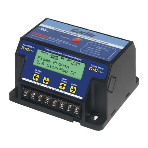
Sfoglia online o scarica il pdf Manuale di installazione e istruzioni per l'uso per Controllore Carlin 60200FR. Carlin 60200FR 8. Gas burner primary control
Anche per Carlin 60200FR: Manuale di installazione e istruzioni per l'uso (9 pagine)
Field Wiring
Wiring must comply with local and national electrical codes, and with the wiring diagram.
Do not connect an external voltage to the thermostat terminals T1 and T2. This will damage the control
and may result in a dangerous operating condition.
FIELD WIRING
GRN
STEP 4
STEP 3
120 VAC
STEP 2
60 HZ
STEP 5
LIMITS
The burner (motor, valve, ignitor, etc.) is prewired at the fac-
tory. The following steps are for field wiring.
Step 1 Remove the 60200FR control from the electrical junc-
tion box to access the terminal strip located on the bottom of
the control.
Step 2 Connect incoming, 120 VAC Hot from the boiler/fur-
nace service switch to the red wire with white stripe attached
to (L1 IN). This will supply constant power to the control for
post purge (motor delay off) operation and display functional-
ity when in standby mode. Note: If a constant 120 VAC power
source from the service switch is not available, connect the
red/white wire attached to (L1 IN) to the black wire attached
to (LIMIT IN).
Replacing the old 60200FR control
Carlin Combustion Technology
GRN
WHT
RED/WHT
BLK
NOTE: Check polarity carefully. If hot and neutral wires
are reversed at appliance power source, the control will
go to Lockout on flame failure.
Step 3 Connect 120 VAC Neutral to the white wire attached
to (L2).
Step 4 Connect the ground wire to the green ground screw
inside the junction box. Connect the "FR Ground Terminal" to
the green ground screw inside the junction box. Confirm that
the junction box is connected to earth ground.
Important: If the ground wire is not secured, the control will
not sense flame properly resulting in nuisance lockouts.
Step 5 Connect the boiler/furnace limit output to the black
wire connected to (LIMIT IN).
1. Remove old control from J-Box
2. Remove Rajah connector from flame rod wire
3. Wire nut the existing wires to the spade provided wires
and connect to control
3