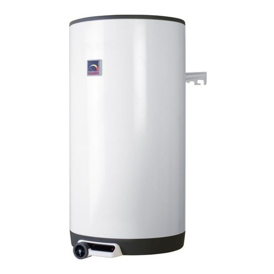
Drazice OKC 125 NTR/HV Manuale di funzionamento e installazione - Pagina 3
Sfoglia online o scarica il pdf Manuale di funzionamento e installazione per Scaldabagno Drazice OKC 125 NTR/HV. Drazice OKC 125 NTR/HV 12. Tank-type water heaters
Anche per Drazice OKC 125 NTR/HV: Manuale di funzionamento e installazione (17 pagine), Manuale operativo e di installazione (20 pagine)

2.
MESSAGE FOR CUSTOMERS
Hot water consumption
Consumption of hot water in households depends on the number of people, amount of sanitary equipment, length,
diameter and insulation of piping in the flat, or on individual habits of users.
The cheapest option of water heating comes at the time when the electricity rate is reduced. Find out in what time
intervals your electricity supplier provides reduced tariff and, depending on that information, select relevant
volume and power input of the heater so that your hot water consumption covered the needs of your household.
Energy saving
Hot utility water reservoir is insulated by means of a top-quality polyurethane foam with zero CFCs content.
Adjust the temperature of the heater's thermostat to that level only that you need to run your home. Thus you will
reduce electricity consumption, as well as the amount of lime sediments on the walls of the receptacle and on the
electric element's pit.
Emergency power consumption
If no heated water is taken from the tank, a small amount of heat leaks. This loss is measured for a period of 24
hours at the temperature of 65°C in the heater, and at 20°C in its ambient area. The resulting value is expressed in
kWh/24h and indicates the amount of power needed to maintain the set temperature.
Data sheet pursuant to Directive No 442/2004 and Appendix No 7
Heater types
OKC 80
OKC 100;
OKC 100 /1m2
OKC 125;
OKC 125 /1m2
OKC 160;
OKC 160 /1m2
OKC 180;
OKC 180 /1m2
OKC 200;
OKC 200 /1m2
OKCE 50
OKCE 80
OKCE 100
OKCE 125
OKCE 160
OKCE 180
OKCE 200
3.
TECHNICAL DESCRIPTION
The heater tank is made of a steel plate and tested by 0.9 MPa overpressure. The inside of the receptacle is
enamelled. A flange is welded onto the bottom of the tank with a flange lid screwed to it. A sealing ring is inserted
between the flange lid and the flange.
Thermowells for placing a heating element and sensors of regulation thermostat and safety fuse are located
in the flange lid. Anode rod is mounted on M8 nut. The water reservoir is insulated by means of polyurethane
foam. Electric wiring is placed underneath the plastic removable cover. The temperature of water can be set using
the thermostat.
In combined versions, a heat exchanger is welded in the pressure tank. The heat exchanger is only intended
for the heating circuit.
4.
OPERATING ACTIVITY
a) Water heating by electric energy
After the heater is connected to electric network, the heating element starts heating water. The element is
turned on and off by a thermostat. After reaching the temperature set, the thermostat switches off the electric circuit
Energy
Heat
efficiency
losses
capacity (l)
class
Wh/24hr/l
C
8,9
C
8,8
C
8,7
C
8,7
C
7,7
B
7
C
9
C
8,9
C
8,8
C
8,7
C
8,7
C
7,7
B
7
Nominal
Time of content
heating (hours)
75
2,5
95
3
120
3,8
147
5
175
5
195
5,5
51
1,5
80
2,5
100
3
125
3,8
152
5
180
5
200
5,5
3
Electricity consumption
Heat losses
for heating of the
contents from 15°C to
65°C in kWh
4,8
6
8
9,6
10,6
12
3
4,8
6
8
9,5
10,6
12
kWh/24hr
0,71
0,88
1,09
1,33
1,39
1,4
0,45
0,71
0,88
1,09
1,33
1,39
1,4
