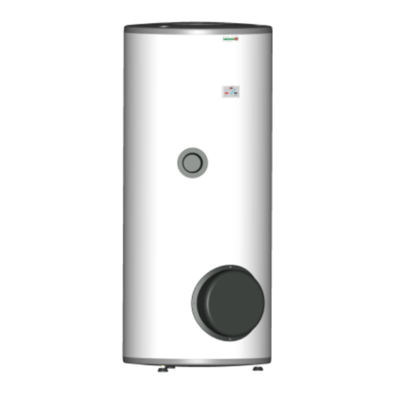
Drazice OKC 300 NTRR Manuale operativo e di installazione - Pagina 3
Sfoglia online o scarica il pdf Manuale operativo e di installazione per Scaldabagno Drazice OKC 300 NTRR. Drazice OKC 300 NTRR 13. Stationary water heaters

2.
PRODUCT DESCRIPTION
The heater tank is welded from a steel sheet; the exchangers from a steel tube and, as a unit, it is entirely coated
with hot water resistant enamel. For additional corrosion protection a magnesium anode is mounted in the upper
part of the heater to adjust the electric potential inside the tank, reducing the risk of corrosion. All types have the
outlets of hot and cold water and a circulation opening welded to them. The tank is insulated with polyurethane
foam of 40 - 65 mm thickness. The heater shell consists of a steel, powder-paint coated, sheet; the connecting parts
are metal coated. The entire heater stands on three rectification screws with a possibility of levelling floor
unevenness within the range of 10 mm. Under a plastic cover on the side of the heater, there is a cleaning and
revision opening ended with a flange; various performance heating units may be mounted into the opening. The
NTR and NTRR series heaters from 200 litre volume are equipped with a 6/4" aperture for in-screwing an
additional TJ heating element. Such version is used when the heater is connected to either a solar system or a
system with a heat pump, to reheat water in the upper part of the heater to the temperature required. The heater is to
be placed on the ground. The tank is tested with pressure of 0.9 Mpa, heat exchanger with 1.5 Mpa.
The NTR version has a heat exchanger located in the bottom part of the heater, and one heating water source is
used for heating.
The NTRR version is equipped with two exchangers for an optional combination of two heating water sources;
both exchangers can be combined in a series. The NTR/BP and NTRR/BP series do not have a heating element.
Heater cannot be used for flow heating of hot water in an exchanger.
Placement and environment type
The heater is placed on the ground, next to the heating water source, or in its vicinity. All connecting distributions
must be properly insulated from heat. It is recommended to use the product in an indoor environment with air
temperatures from +2 to 45°C and a maximum relative humidity of 80%.
3.
IMPORTANT NOTICES
- Without a proof issued by a professional company about performed electrical and plumbing fixture the
warranty shall be void.
- The Mg anode has to be checked regularly and exchanged, if needed.
- No stop valves can be put between the heater and the safety valve.
- All outlets of hot water must be equipped with a combination faucet.
- Before the first filling of water heater it is recommended to tighten the nuts of the flange joint of the tank.
- It is not allowed to handle the thermostat, aside from temperature resetting with a control button.
- All electric installation handling, setting, and regulation feature exchange, may only be implemented by a service
company.
The thermal fuse must not be turned off! In case of a thermostat defect, the thermal fuse interrupts electric
-
power supply to the heating element if the water temperature in the heater exceeds 95°C.
- As an exception, the thermal fuse may also switch off due to water overheating caused by overheating the hot
water heating system boiler (in case of a combined heater).
We recommend you operate the heater with one type of energy. In case a solar system is connected to the
-
bottom exchanger, it is necessary to connect a TJ 6/4" line element in the coupling above the heater for potential
additional heating.
4.
PUTTING THE HEATER INTO OPERATION
After connecting a heater to the water main, the hot water heating system, the electric network, and after testing its
safety valve (based on the valve manual attached), the heater may be put into operation.
Procedure:
Check both water and electric installation; for combined heaters, check the installation to a hot water heating
a)
system. Check proper placement of operating and safety thermostat sensors. The sensors must be inserted all
the way in; first the thermostat and then the safety fuse.
b)
Open the hot water valve on the combination faucet;
c)
open the cold water inlet valve to the heater;
d)
when the water starts flowing through the hot water valve, the filling of the heater is finished and the valve
needs to be closed;
e)
Should a leak (of the flange lid) occur, we recommend tightening the screws of the flange lid;
f)
Fasten the electric installation cover;
3
