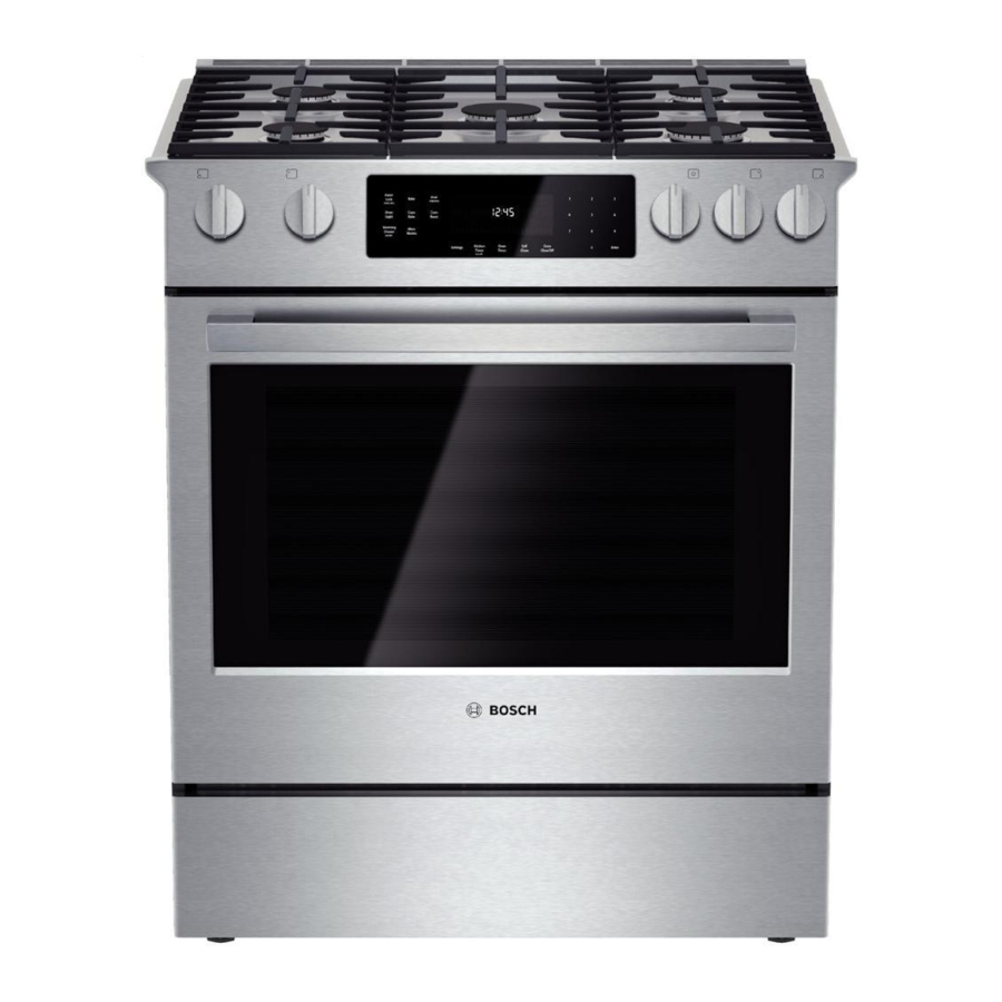
Bosch Vision 800 Series Manuale di servizio - Pagina 25
Sfoglia online o scarica il pdf Manuale di servizio per Forno Bosch Vision 800 Series. Bosch Vision 800 Series 43. Gas slide-in ranges
Anche per Bosch Vision 800 Series: Manuale di istruzioni per l'uso (40 pagine), Dimensioni e specifiche (2 pagine), Manuale di installazione (6 pagine), Manuale di istruzioni per l'installazione (28 pagine), Manuale di servizio (36 pagine)

58300000202443_ARA_EN_C
Figure 31 Screws securing the ring element to the rear wall of the cavity
3. Remove the screws securing the ring element to the cavity
wall, then carefully pull the element forward.
4. Disconnect the wires from the ring element terminals, being
careful not to drop the wires behind the oven.
If the wires are too short to disconnect from the front,
continue with step 5.
If the wires were successfully disconnected, skip to step 8.
5. Remove the screws securing the right and left side trim pieces
to the cabinetry.
6. Carefully slide the oven out of the cutout to gain access to the
ring element terminals from the rear of the unit.
7. Disconnect the wire leads from the terminals.
8. Install the new element and reinstall the baffle.
9. Restore power and test operation.
10. If necessary, slide the oven back into the cutout and reinstall
trim.
6.6.3
Replacing the Convection Fan Motor
1. Follow steps 1-3 in the Replacing the Convection Fan Blade
section.
2. Remove the washer located behind the blade and set aside.
3. Remove the screws securing the right and left side trim pieces
to the cabinetry.
Copyright by BSH Home Appliances Corporation
This material is intended for the sole use of BSH authorized persons and may contain confidential and proprietary information. Any unauthorized review, use, copying, disclosure, or distribution in any format is prohibited.
JANUARY 2018
4. Carefully slide the oven out of the cutout to gain access to the
motor from the rear of the unit.
5. Remove the rear housing panel.
6. Disconnect the wires from the motor terminals.
7. Remove the screws securing the fan motor.
8. Three sheet metal tabs hold the motor in position after the
screws are removed; bend the tabs outward, using a flat blade
screwdriver or pliers, then remove the motor.
Figure 32 Sheet metal tabs for securing convection fan motor to rear of oven
9. Install the new motor, being sure to bend the three sheet metal
tabs back in.
10. Reinstall the fan blade and baffle.
11. Restore power and test operation.
6.7
Broil Element
The 240V 3800W broil (upper) element is attached to a reflector,
which helps to direct the heat evenly toward the food.
Refer to the Element Strip Diagram section to test the broil element at
the control module. A Broil Element Relay Test is also available in
Service mode. See the Service Mode section for details.
If the wires are disconnected from the element terminals, an
ohmmeter can be used to check for resistance of ~15 ohms.
1901 Main St ▪ Suite 600 ▪ Irvine, CA 92614
Service Manual for Bosch 800 Series Built-in Wall Ovens
Page 25 of 43
800 944-2904
