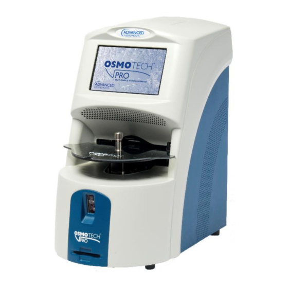
Advanced Instruments OsmoTECH PRO Manuale di avvio rapido - Pagina 3
Sfoglia online o scarica il pdf Manuale di avvio rapido per Apparecchiature mediche Advanced Instruments OsmoTECH PRO. Advanced Instruments OsmoTECH PRO 4. Sample probe motor
Anche per Advanced Instruments OsmoTECH PRO: Manuale di avvio rapido (5 pagine)

Removing the sample probe motor
1.
Remove the sample probe motor's wire leads from
the two cable clamps [E] and the three cable clips
[F].
2.
Remove the hex nut and washer [G] that secure the
sample probe motor's lead‑screw to the top of the
osmometer module top plate.
3.
Hold the movable plate that secures the body of the
sample probe motor and remove the set‑screw [H]
from each side of the osmometer module top plate.
Keep hold of the movable plate once the set‑screws
are removed to prevent the plate from dropping.
H
E
F
G
OsmoTECH® PRO Sample Probe Motor
4.
Gently lower the movable plate until it rests on top
of the stripper bracket.
5.
Remove the two socket head cap screws [I] and
washers that mount the sample probe motor to the
movable plate.
Replacing the sample probe motor
Refer to
Removing the sample probe motor
and callouts.
1.
Secure the replacement sample probe motor to the
movable plate using the two socket head cap
screws and washers [I].
2.
Lift the movable plate until the adapter on the end
of the sample probe motor's lead‑screw enters the
osmometer module top plate and the adapter's
threads are extending beyond the top of the plate.
3.
Secure—but do not fully tighten—the adapter
threads with the hex nut and washers [G].
4.
Partially thread the two set‑screws [H] into the
sides of the osmometer module top plate.
5.
Lift the movable plate that secures the sample
probe motor until the lead‑screw's adapter is
properly positioned inside the osmometer module
top plate.
6.
Hold the movable plate and tighten the two set‑
screws [H].
7.
Tighten the hex nut to secure the adapter's threads
[G].
If the sample probe motor's lead‑screw turns as the
nut is being tightened, then the two sets‑screws are
not tight enough.
Replacement Procedure
I
for images
Page 3 222104PM Rev 0
