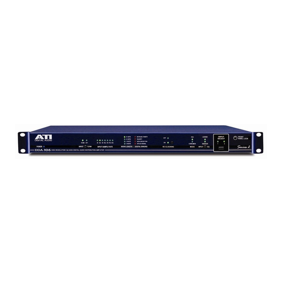
ATI Technologies DDA224-BNC Manuale operativo e di manutenzione - Pagina 6
Sfoglia online o scarica il pdf Manuale operativo e di manutenzione per Amplificatore ATI Technologies DDA224-BNC. ATI Technologies DDA224-BNC 8. Aes/ebu digital audio distribution amplifiers

POWER
If it is necessary to convert a unit wired for 115VAC to 230VAC operation, unplug
the unit from the power source, remove the four cover mounting screws and
locate the E1 jumpers next to the power transformer. Clip the jumpers 1-2 and 3-
4 (don't unsolder), jumper from 2-3 carefully soldering together the free ends of
2-3 previously clipped. This procedure is recommended to avoid soldering
damage to the multi-layer PC board.
WIRING
XLR types require special controlled impedance, 110 ohm, low loss, foil shielded,
twisted pair cables. Standard audio cable is not recommended except for runs of
only a few feet. Belden and most other cable manufacturers offer special digital
audio cabling for this application. With equalization, cable runs of 300 meters
(about 1000 feet) should be achievable. BNC types use 75-ohm coax (RG59).
Select a cable for losses less than 20dB at 12MHz (for data rates up to 96kHz) at
the maximum distance you require. Runs up to 1000 meters should be readily
achievable with low loss coax.
INPUT CABLE EQUALIZATION
If there is an unusually long (more than a few hundred feet) cable connection
between a particular AES/EBU data source and the DDA or DSA, it may be
necessary to equalize the cable response. Equalization would be indicated if it is
not possible to lock onto a known good signal source and obtain a stable reading
of the DDA input sample rate as evidenced by the front panel indicators.
(The following procedure uses the front panel displays of the DDA to verify
correct operation. Note that DSA units have no front panel display; therefore,
Input Cable Equalization adjustment should be performed with a known-good
AES tester connected to any of the DSA unit's outputs.)
1. Apply a known good AES/EBU digital signal with sample rate of 96, 88.2, 48,
44.1, or 32 kHz to the source end of the cable. (You can validate the source by
temporarily co-locating the DDA with the signal source, connecting them together
with a short cable and noting that all red LEDs are off, all green LEDs are on and
the correct sample rate is steadily displayed.)
2. The factory default setting for the front panel equalizer control(s) is fully
counterclockwise. With a small screwdriver, slowly turn it clockwise, pausing after
each half turn for three seconds to allow the displays to update. Note the first
position at which all red LEDs are off, all green LEDs are on and the sample rate
is displayed steadily.
3. Continue to turn the control clockwise, counting turns, until the conditions of 2
above are no longer obtained.
4. Turn the control counterclockwise by half the number of turns counted in 3.
above. This is the optimum setting for the installed cable length and sample rate.
Audio Technologies Inc.
• Tel: 856-626-3480
•
Fax: 856-504-0220
•
www.
audio.com
