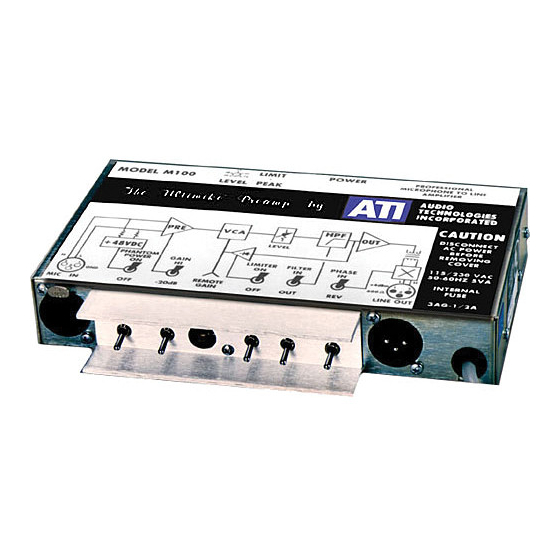
ATI Technologies M100 Manuale operativo e di manutenzione - Pagina 3
Sfoglia online o scarica il pdf Manuale operativo e di manutenzione per Amplificatore ATI Technologies M100. ATI Technologies M100 8. Ati ultimike m100 microphone amplifier operating and maintenance manual
Anche per ATI Technologies M100: Manuale operativo e di manutenzione (9 pagine)

A4A makes a switchable, unity gain high pass filter with two-pole response of -3dB at
150 Hz and rolling off 40 dB at 15 Hz. The filter is switched in or out of the circuit with
S4.
The output line driver A4B and output transformer T2 provide 16 dB of gain and the total
isolation, faraday shielding, RF immunity and ease of use of a true transformer coupled
balanced output. A unique feedback technique totally avoids the transformer's
characteristic limitations of high distortion, poor response and hum pickup. Typical
output distortion measurements made at both peak (+22 dBm) and nominal (+4 dBm)
levels barely exceed generator residuals from 20 to 20,000 Hz. Hum pickup from the
power supply is well below the noise level and low frequency response is greatly
extended. The output is protected from short circuits but will drive over one-half mile of
shielded cable with less than 1 dB of signal rolloff at 20,000 Hz.
We deliberately omit the output connector pin 1 ground lift jumper (W4). If you insist on
setting up loops by grounding your cable shields at both ends, you can connect the shield
to the output connector plug shell.
A5A and A5B make an active full wave rectifier and filter to drive the limiter. R5 sets a
limiting threshold corresponding to an output level of +14 dBm. The limiter has a soft
knee and a gentle slope of about 4:1 so that continued peaks greater that 10 dB above the
nominal output will cause a slow reduction in gain. If the limiter switch is off, the front
yellow LED will light on sustained peaks to tell you to use the limiter or to reduce the
gain. With the limiter on, an occasional flash will indicate normal operation but
sustained illumination is an indication that you are reaching the end of the gain reduction
range.
Q5 is a constant current driver for the limiter LDR, which can be controlled by an
external 10 Kohm potentiometer plugged into the phono jack type connector. The remote
gain control has an adjustment range of 0 to –15 dB and does not interact with the limiter
except that both share the 24 dB total gain reduction range of the LDR. The remote gain
control is DC operated and can be located a considerable distance from the M100 without
noise pickup.
A5C and A5D form a 40 kHz DC-to-DC converter to efficiently generate the +48 VDC
microphone phantom power.
Your M100 operates from an internal, double-filtered bipolar 16 VDC supply, which uses
a couple of unique regulated devices called zener diodes. In contrast to fancy three
terminal regulators, these devices will live through power line trash and transients and
simultaneously protect your valuable circuitry. The supply is designed for minimum
susceptibility to power line conducted RF and hash with bypassed ferrite beads, RC
primary side bypasses and a mu-metal shielded, non-concentric wound, semi-toroidal
power transformer. A large board mounted 1/2A AC line fuse protects your M100 but
can make taking off the cover with the AC line still connected into a very exciting
adventure.
Audio Technologies Inc. | 154 Cooper Road #902 | West Berlin, NJ 08091 | Voice 856-719-9900 | Fax 856-719-9903 | www.
audio.com
