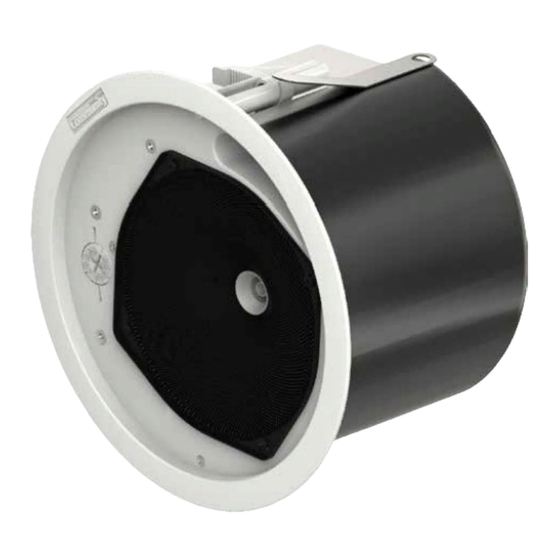
Community C4 Manuale di installazione e funzionamento - Pagina 13
Sfoglia online o scarica il pdf Manuale di installazione e funzionamento per Altoparlanti Community C4. Community C4 20. 4.5", 6.5", 8" full-range c series coaxial ceiling loudspeakers
Anche per Community C4: Manuale di installazione e funzionamento (16 pagine)

Installing the Loudspeaker in the Ceiling
General
Lay out the loudspeaker locations according
to the requirements of the speci ic installa-
tion and in compliance with applicable safety
and building codes. It is beyond the scope of
this manual to provide guidance in this area.
Community does, however, offer our Forecast-
er HD Distributed Ceiling System Software to
assist you in distributed loudspeaker system
design. Please visit the Product Selection area
of Community's website for this software.
We also encourage using the provided seis-
mic safety tabs to secure the back cans to the
building structure. Again, please be guided by
applicable building codes here; Community
cannot provide detailed rigging instructions
due to the wide global variations in such
codes and practices.
Procedure (for suspended ceiling)
Note: The optimum situation for installation
is into a ceiling where the suspension grid is
installed and the tiles have not yet been placed.
Community designed this series to facilitate
installation into an already-placed ceiling, and
we are writing the instructions to conform to
this more restrictive condition. So when we say
something like, "pass the tile bridge support
rails through the loudspeaker cutout," and
in your situation the adjacent space is unob-
structed, of course you should feel free to use
the more sensible alternative and just drop the
rails into place.
1. Mark the hole location on the ceiling tiles
and, using the cutout template provided with
your Commercial Design Series loudspeakers,
cut a hole to the precise size. See Figure 10.
2. Insert the Tile Bridge Support Rails
through the can cutout and position them
across the rails on either side of the cutout,
approximately as far apart as the Bridge Rail
Spacer Bars. Then insert the pair of spacer
bars and clip them over the tile bridge sup-
port rails as shown in Figure 11.
Community Commercial Design Series
Figure 10. Cutout template dimensions
Bridge Rail
Spacer Bars
Figure 11. Positioning the Tile Bridge
Support Rails and Bridge Rail Spacer Bars
3. Make sure mounting clamps are parked
tight against sides of back can before slid-
ing the loudspeaker into the hole, aligning
it so that the mounting clamps are nearest
to the two bridge support rails, labels on
the loudspeaker face indicate the position
of the mount clamps and the required align-
ment. Before sliding the back can into the
ceiling hole, slightly bend each Drop-Stop™
tab outward from the back can 1/2 inch (12
mm). When you press the can fully into place,
the two spring-loaded Drop-Stop™ tabs will
spread atop the bridge support rails, and
you may hear them "snap" into position; you
can now continue without having to hold the
loudspeaker in place. The Drop-Stop tabs are
Installation and Operation Manual
Tile Bridge
Support Rails
Page 13
