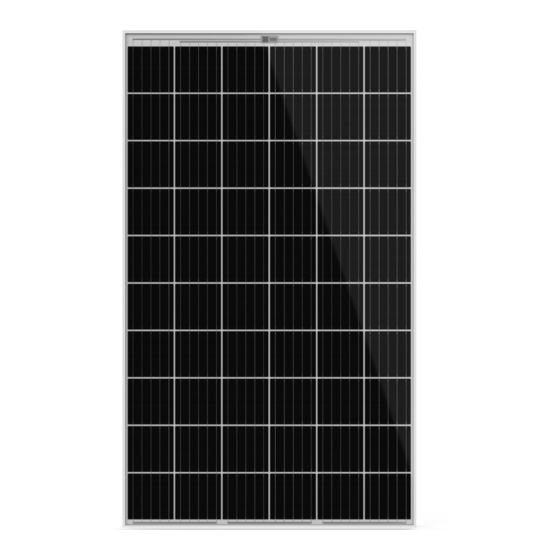
Aleo S83 sol Manuale di installazione - Pagina 12
Sfoglia online o scarica il pdf Manuale di installazione per Unità di controllo Aleo S83 sol. Aleo S83 sol 20.
Anche per Aleo S83 sol: Manuale di installazione (20 pagine)

10.4.2 Modules with Solrif® frames
NOTE
Avoid screw mounting for Solrif
mount Solrif
modules with the Solrif
®
system.
10.4.3 Tightening torque for screw mounting
For M8 stainless steel screws, use a maximum torque of
24 Nm.
6
10.5
Insertion mounting
10.5.1 Modules with standard frames
Observe the manufacturer's instructions for the mounting
system. Use the earthing holes for the potential equalisation.
Although edge-to-edge mounting is possible (see also
Ch. 8.4.1: „Intervals between modules with standard
frames"), aleo solar recommends mounting at intervals.
10.5.2 Modules with Solrif
Only mount modules with Solrif
mounting system.
10.6
Load levels
A load can be a pressure load as well as a a suction load.
Loads from snow and wind are grouped into three levels,
which need to be taken into account wherever the module
is installed. Higher load levels make the requirements for
proper installation more stringent. The values listed below
assume an appropriate installation.
10.6.2 Permissible loads for modules with standard
frames 35mm
Load level
Permissible
pressure
1400 Pa 7
Load level I
Load level II
3900 Pa
Load level III
5400 Pa
10.6.3. Permissible loads for modules with Solrif
Load level
Permissible
pressure
Load level I
2400 Pa
Load level III
5400 Pa
Please observe the instructions from Schweizer for the
mounting of modules with Solrif frame.
You can find the manual on the website from Ernst Schwei-
zer AG Metallbau or on aleo solar website:
www.aleo-solar.com.
5
The total length is 22.5 mm. The distance between the hole centres is 13.5 mm.
6
This applies to unlubricated screws with standard thread and strength class of 8.8
(minimum breaking load 29.2 kN).
7
based on IEC 61215
Page 12/20
modules. Only
®
mounting
®
frames
®
frames with the Solrif
®
Permissible
suction
1400 Pa 7
2400 Pa
2400 Pa
frames
®
Permissible
suction
2400 Pa
2400 Pa
10.6.4 Permissible loads for modules with standard
frames 42mm
Load level
Load level I
Load level II
Load level III
Load level IV
10.6.4 Snow Load
For snow loads above 3900 Pa, suitable measures must be
taken to ensure that slipping snow loads do not damage
the lower module frame. This applies to portrait mounting
and clamping on the long side (observing the permitted
clamping positions, see chapter 10.8).
Possible measures are: Snow hooks on the lower module
frame, frame fixings or an additional substructure rail with
standard end clamp, in the middle of the lower frame part.
®
aleo solar GmbH | Marius-Eriksen-Straße 1 | 17291 Prenzlau | Germany | [email protected]
Permissible
Permissible
pressure
suction
2400 Pa
2400 Pa
3900 Pa
2400 Pa
5400 Pa
2400 Pa
8000 Pa
5400 Pa
Quick Reference Manual Rel. 4.7, 08/2020, EN
