Dresser iCIP 300 Series Manuale delle procedure di installazione e funzionamento - Pagina 5
Sfoglia online o scarica il pdf Manuale delle procedure di installazione e funzionamento per Pompa dell'acqua Dresser iCIP 300 Series. Dresser iCIP 300 Series 14. Intelligent chemical injection pump
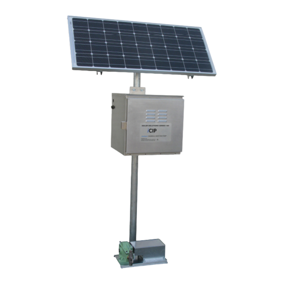
security latch, and front ventilation. The enclosures are
available in 1-5 battery types that are rated and meet NEMA
3R-rating. For 1, 2, 3 battery enclosures use the two U-Bolts
provided, to mount the empty battery enclosure firmly to the
secured 6 foot pole, approximately three feet from the
ground to the underside of the enclosure. Over tightening of
the U-Bolts should be avoided. The 4 battery enclosure
is a top hinge type chest which will lay on the ground. The
motor controller, solar converter and terminal strip come
pre-assembled on the Sub Panel from Dresser. This Sub
Panel is located on the upper back wall of the Battery
Enclosure. It has been secured and is offset from the back
mounting surface of the enclosure using four #10-32UNC
Studs.
Motor and Pump Install
Connect the DC motor cable end (circular connector) to the
mating connector (panel mount) on the battery enclosure.
Reference Figure 7. A standard 6 foot motor wire harness
comes pre-assembled using a IP-67 Mil-Spec all weather
12-Pin connecting receptacle. This connection can easily
be connected and disconnected for ease of installation or
relocation. Reference Figure 9.
72.0 in. ± .50
Figure 9
Motor Wiring Extension Harness
An additional 14 foot Wiring Harness Extension for 24 Volt
motor is available only through Dresser Solar Solutions
Manufacturing facilities. P/N SP2100 Extension Cable will
be provided with (2) IP-67 Mil-Spec all weather 12-Pin
connecting receptacles.
Battery Wiring Install
Once the enclosure has been mounted onto the pole or
placed on the ground, the battery(s) can then be inserted
into the battery enclosure. Reference figures 10-12 and
schematics for wiring and installation steps.
On multiple battery installations, a ground wire has been
provided to be connected from battery negative to battery
negative. The black wire should be connected from a
negative battery post to the negative connection on the
terminal block on the enclosure backplate.
Pos +
Figure 10 – Single Battery
Pos +
Figure 12 – Triple Battery
Positive Cable End
Supply Power to iCIP
Connect color coded cable(s) from battery to same cable
with color coded connector within enclosure that terminates
to terminal block.
Connect color coded cable(s) from solar panel to same color
coded connector within enclosure that terminates to terminal
block.
The system should now be operational. The LED display on
the controller should be illuminated.
5
Neg –
Neg –
Pos +
Figure 11 – Double Battery
™