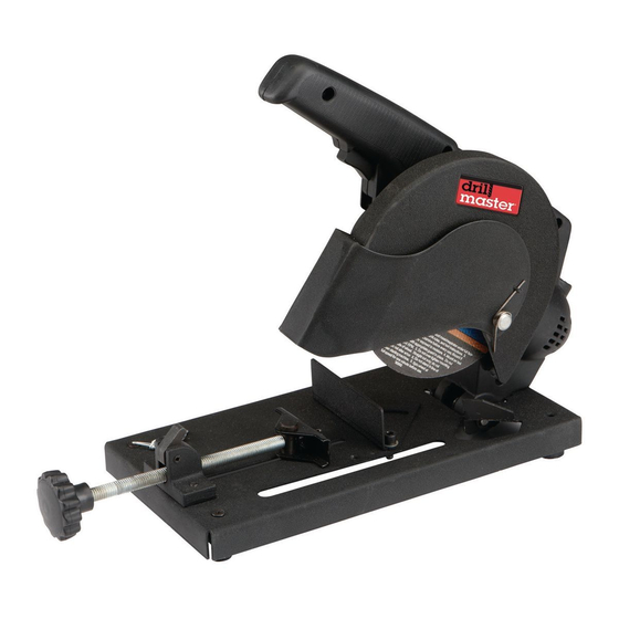
Drill Master 61204 Manuale d'uso e istruzioni di sicurezza - Pagina 7
Sfoglia online o scarica il pdf Manuale d'uso e istruzioni di sicurezza per Sega Drill Master 61204. Drill Master 61204 16. 120 volt 6" cut-off saw
Anche per Drill Master 61204: Manuale d'uso e istruzioni di sicurezza (16 pagine)
Operating instructions
read the EntirE iMpOrtant SaFEty inFOrMatiOn section at the beginning of this
manual including all text under subheadings therein before set up or use of this product.
tool Set up
tO prEVEnt SEriOuS inJury FrOM acciDEntaL OpEratiOn:
release the pressure and unplug the tool from its electrical outlet before
assembling or making any adjustments to the tool.
tO prEVEnt SEriOuS inJury:
DO nOt OpEratE WitH any GuarD DiSaBLED, DaMaGED, Or rEMOVED.
installing a cut-Off (Grinding) Wheel
1. The Grinding Wheel MUST be:
• rated to at least 10,000 RPM.
• no larger than 6" in diameter.
• fitted with a 5/8", 7/8" (changeable)
round arbor hole.
• suitable for edge grinding, not surface grinding.
• dry and clean.
• proven undamaged by inspection and
by the ring-test explained below.
2. Closely inspect the new wheel before mounting it.
Perform a ring-test on the wheel
a. Suspend wheel using a dowel or
finger through the arbor hole.
Hang
Wheel
from
Dowel
tap
Wheel
Here
b. Tap the flat side of the wheel with a light non-
metallic object, such as a screwdriver handle,
at a point 45° from the vertical center line on
each side of the wheel and 1 – 2 inches from
the edge of the wheel (see Illustration).
c. Rotate the wheel 90° and repeat the test
until the entire wheel has been checked.
d. An undamaged wheel will ring with a
clear tone. If cracked, there will be a
dead sound and not a clear ring.
61204
45°
45°
45°
45°
V
V
E
E
r
r
t
t
i
i
c
c
a
a
L
L
c
c
E
E
n
n
t
t
E
E
r
r
45°
45°
45°
45°
For technical questions, please call 1-888-866-5797.
3. Release the Safety Chain from the securing
pin (see Figure a) and guide the Housing
to rest at its full upward position.
Safety
chain
Figure a: Safety chain
4. Open the Swing Guard all the way,
exposing the Grinding Wheel, Outer
Flange (29) and Arbor Bolt (30).
5. As shown in Figure B, use the supplied
Flat Wrench (44) to hold the Spindle
in place and use the supplied Sleeve
Wrench to loosen the Arbor Bolt.
Swing
Guard
Figure B: removing the arbor Bolt
6. Remove the Arbor Bolt, the Outer Flange and the
old Grinding Wheel, noting the orientation of each.
Securing
pin
Flat
Wrench
Sleeve
Wrench
Page 7