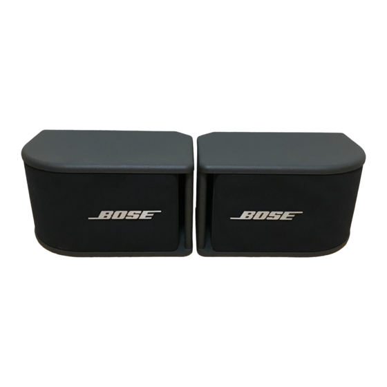
Bose 300PM Manuale - Pagina 6
Sfoglia online o scarica il pdf Manuale per Altoparlanti Bose 300PM. Bose 300PM 13.
Anche per Bose 300PM: Manuale di servizio (16 pagine)

Power Amplifier
-
+
+
-
Frequency
Generator
Figure 1. Model 300PM Loudspeaker Test
Setup Diagram
Note: Refer to Figure 3. Model 300PM
Driver Wiring Diagram for the following
procedure.
1. Phase test
1.1 Remove the speaker grille using
Disassembly/Assembly procedure 1.
1.2 Observing polarity, apply a +6Vdc level
to the input terminals on the rear of the
loudspeaker. The speaker drivers should
both move outward.
1.3 Replace the grille using Disassembly/
Assembly procedure 2.
Note: Refer to Figure 1. Model 300PM
Loudspeaker test setup diagram, for the
following tests.
2. Rub and tick test
2.1 Remove the grille using Disassembly/
Assembly procedure 1.
2.2 Apply a 6Vrms, 10Hz signal to the input
terminals on the rear of the speaker
cabinet.
2.3 Listen carefully for any buzzes, rattles,
or other extraneous noises from the drivers
or trim parts.
Note: There is a normal suspension noise.
To distinguish between a rub or a tick and
suspension noise, displace the driver cone
TEST PROCEDURES
-
+
+
-
DMM
+
Loudspeaker
-
slightly with a finger. If the noise stays the
same, it is suspension noise.
2.4 Replace the grille using Disassembly/
Assembly procedure 2.
3. Air leak test
3.1 Remove the grille using Disassembly/
Assembly procedure 1.
3.2 Apply a 6Vrms, 60Hz signal to the input
terminals on the rear of the speaker
cabinet. Leave the speaker port open.
3.3 Test duration should be 5 seconds
minimum.
3.4 Listen carefully for air leaks along all
glue joints, at the binding post connector,
and at both transducer mounting locations.
Air leaks will be heard as a hissing or
sputtering sound. All repairs must be
hidden.
3.5 Replace the grille using Disassembly/
Assembly procedure 2.
4. Power sweep test
4.1 Apply a 6Vrms, 10Hz signal to the input
terminals on the rear of the speaker
cabinet. Leave the speaker port open.
4.2 Sweep the input frequency from 10Hz
to 3kHz.
4.3 Reduce the input voltage level to
4Vrms and sweep the oscillator from 3kHz
to 5kHz.
Note: The whooshing noise from the port
at approximately 60Hz is acceptable.
4.4 Replace any transducer that has a
buzzing noise. There shall not be any
buzzes or rattles from the internal
connecting wires or components.
Redress any buzzing wires.
6
