Bose ACOUSTIMASS PRO Manuale - Pagina 5
Sfoglia online o scarica il pdf Manuale per Altoparlanti Bose ACOUSTIMASS PRO. Bose ACOUSTIMASS PRO 19.
DISASSEMBLY/ASSEMBLY PROCEDURES
Note: Numbers in parentheses correspond
to the item call outs in Figure 1, 2, 3, 4.
1. Amplifier Removal
1.1 Remove the sixteen screws (8) that
secure the amplifier (3) to the cabinet.
1.2 Lift the amplifier out of the enclosure.
Disconnect the ground lug from the ampli-
fier chassis and the two output wires from
the capacitor (14) and inductor (13).
2. Amplifier Replacement
2.1 Connect the ground wire (green) to the
amplifier (3) chassis. Connect the red wire
to the capacitor (14) and the black wire to
the inductor (13).
2.2 Replace the sixteen screws (8) that
secure the amplifier to the cabinet.
3. Woofer Removal
3.1 Perform procedure 1 first.
3.2 Remove the eight screws (8) that
secure the woofer (1) to the cabinet.
3.3 Lift the woofer out and remove the two
wires connected to it.
4. Woofer Replacement
4.1 Connect the red wire to the positive
and the black wire to the negative terminal
of the woofer (1).
4.2 Replace the eight screws (8) that
secure the woofer to the cabinet.
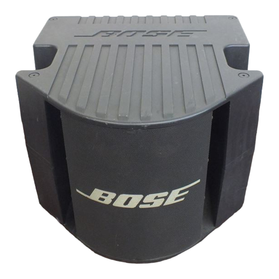
5. Grille Removal
5.1 Remove the eight screws (7) that
secure the grille (4) to the cabinet.
5.2 Pull the grille off.
Note: On some units the screws are
secured with loctite. Use MEK solvent to
remove the screws.
(Figures 1, 2, 3, 4)
6. Grille Replacement
6.1 Align the grille (4) with the cabinet so
that the Bose
as the label on the amplifier.
6.2 Replace the eight screws (7) that
secure the grille to the cabinet.
7. Driver Removal
7.1 Perform procedure 5 first.
7.2 Remove the three screws (6) that
secure the driver (2) to the cabinet.
7.3 Lift the driver out from the cabinet and
remove the two wires attached to it.
Note: On some units the screws are
secured with loctite. Use MEK solvent to
remove the screws.
8. Driver Replacement
8.1 Connect the two wires to the driver (2).
Refer to the wiring diagram on page 18.
8.2 Replace the three screws (6) that
secure the driver to the cabinet.
9. Amplifier Cover Removal
9.1 Perform procedure 1 first.
9.2 Remove the six screws (A) that secure
the top cover to the chassis and lift the top
cover off.
10. Amplifier Cover Replacement
10.1 Align the top cover to the chassis and
replace the six screws (A) that secure the
top cover to the chassis.
11. Amplifier Chassis Cover Removal
11.1 Perform procedure 1 and 9 first.
11.2 Remove the ten screws (E) that are
located on each side of the chassis and the
ten screws (F) that are located on the top of
the chassis.
5
®
logo is in the same direction