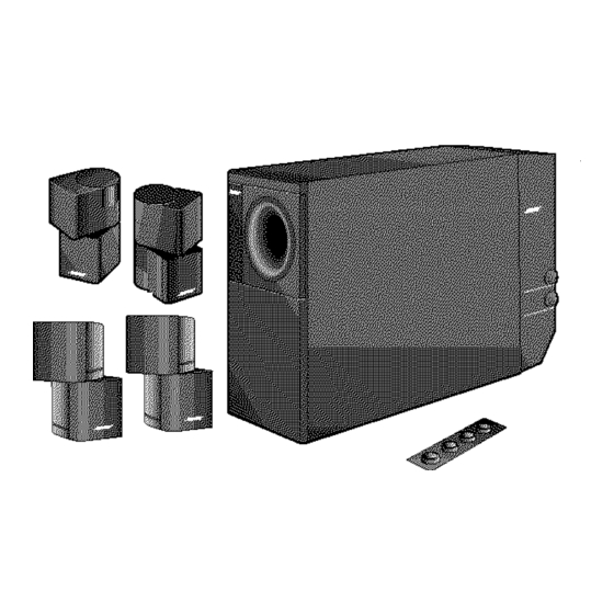
Bose Acoustimass 5 Manuale d'uso - Pagina 17
Sfoglia online o scarica il pdf Manuale d'uso per Sistema di altoparlanti Bose Acoustimass 5. Bose Acoustimass 5 22. Powered speaker system
Anche per Bose Acoustimass 5: Manuale d'uso (9 pagine), Manuale d'uso (16 pagine), Manuale d'uso (22 pagine)

Connecting the Acoustimass
Figure 17
Connecting the speakers to your
Model 5 music center
Figure 18
Setting up the remote control
AM262838_00_V.pdf
module to the Model 5 music center
®
AUDIO
INPUT
RIGHT
OUTPUTS
TO
CUBE
SPEAKERS
LEFT
OFF
POWER
ON
Note: To extend the length of the cables, use the supplied 50-foot extension cable (shown
as the dotted line above). This cable connects between the 30-foot audio input cable and
the music center.
To connect the Acoustimass 5 or 20 powered speakers to your system, refer to Figure 17 and
follow these steps:
1. Using the supplied 30-foot audio input cable, insert the round DIN connector into the
Acoustimass module.
2. At the other end of that cable, connect the RCA plugs to SPEAKERS B and the 3.5 stereo
mini plug to SYSTEM CONTROL 2 on the music center.
Setting up the remote control
You need to set up a second remote control to operate the SPEAKERS B outputs.
1. Remove the remote control battery cover and locate the miniature switches (Figure 18).
2. Make sure that the house code settings (switches 1, 2, 3, 4) match those on your first
remote.
3. Set switches 5 down and 6 up for SPEAKERS B.
Connecting power to your system
CAUTION : If you purchased a dual-voltage system, it is important that you set the speakers
to the correct voltage. To do this, refer to "Selecting the correct voltage" on page 6.
Follow these steps to connect power to your Acoustimass powered speaker system:
1. Plug the power cord from the Acoustimass module into an AC power (mains) outlet.
2. Insert the power cord of the Lifestyle
3. Turn the Acoustimass module power switch to the On position.
December 20, 2001
L
L
FIXED
L
R
1
L
FIXED
R
SYSTEM
A
B
R
SPEAKE RS
CONTRO L
REC
PLAY
OUTPUT
TAPE
VIDEO
2
AUX
OUTPUT
SOUND
A
B
R
SPEA KERS
ANTENN A
REC
SEE INSTRUC
PLAY
OUTP UT
TAPE
AUX
VIDEO
SOUN D
OUTP UT
ON
K
40
l
2 3 4
5 6 7 8
®
system into an AC power (mains) outlet.
Setting Up
POWER
12VAC
IN
1.0A
1
POWE
SYST EM
12VAC
CONT ROL
1.0A
TION MANUAL
2
ANTE NNA
SEE INSTR
UCTIO N MANU
15
