Bose FreeSpace IZA 2120-HZ Manuale di installazione e funzionamento - Pagina 17
Sfoglia online o scarica il pdf Manuale di installazione e funzionamento per Amplificatore Bose FreeSpace IZA 2120-HZ. Bose FreeSpace IZA 2120-HZ 48. Integrated / zone amplifiers
Anche per Bose FreeSpace IZA 2120-HZ: Manuale d'installazione e d'uso (48 pagine)

- 1. Table of Contents
- 2. Freespace® Iza 2120-Lz / Iza 2120-Hz Integrated Zone Amplifier
- 3. Iza 2120-Lz Rear Panel
- 4. Za 2120-Lza/Hza Rear Panel
- 5. Remote Volume Control
- 6. Connecting the CC-1 to a Freespace® Amplifier
- 7. Connecting an Iza 2120-Lz/Hz Amplifier to a Za 2120-Lza/Hza Amplifier
- 8. Troubleshooting
pro.Bose.com
FreeSpace® IZA 2120-LZ
The four-input IZA 2120-LZ mixer amplifier is optimized for low-impedance stereo or mono applications. It
supports loudspeaker EQs for the FreeSpace DS 16, DS 40, and the larger DS 100, and RoomMatch
RMU105.
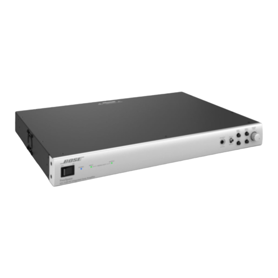
IZA 2120-LZ Front Panel
Figure 2. FreeSpace IZA 2120-LZ amplifier front panel
q
w e
q POWER Switch - ON/OFF AC power.
w POWER LED - Solid blue LED indicates the unit is ON. Blinking blue LED indicates the unit is in standby
mode.
e INPUT SIGNAL LED - LED is green from –37 dBu to 11 dBu, LED goes red over 11 dBu. MASTER LEVEL
set at 5.
r OUTPUT LIMIT LED - LED is green from –46 dBFS to –2 dBFS, LED goes red over –2 dBFS,
approximately 80 W/channel. For each output, 120 watts is 0 dBFS.
t AUX INPUT - 1/8" (3.5 mm) stereo line-level input connector. A cable insertion mutes INPUT A and
INPUT B for priority override. Pages can still be made from the PAGE INPUT. AUX INPUT does not have
any gain adjustment, therefore, all gain adjustments must be done from the external source device.
y INPUT A/B Switch - Allows selection of rear line-input channels A or B.
u TREBLE/BASS Controls - Allows tonal adjustments of both outputs simultaneously. These are 1st order
shelving filters that provide ±6 dB adjustment at 7 kHz and above (TREBLE) and 100 Hz and below
(BASS). They have a slope of approximately 6 dB/octave.
i MASTER LEVEL Control - Controls the overall system volume for both the loudspeakers and the AUX
OUTPUT when the AUX OUTPUT DIP switch is set to VARIABLE. If the AUX OUTPUT DIP switch is set
to FIXED, the AUX OUTPUT maintains maximum level.
Note: When using a REMOTE volume connection, the front panel MASTER LEVEL control becomes
disabled. See "Remote Control Connections" on page 26 for more details.
r
Front and Rear Panels
t
y u
i
Installation Guide - 17
Utility
®
