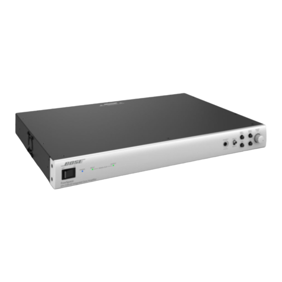
Bose FreeSpace IZA 2120-HZ Manuale di installazione e funzionamento - Pagina 41
Sfoglia online o scarica il pdf Manuale di installazione e funzionamento per Amplificatore Bose FreeSpace IZA 2120-HZ. Bose FreeSpace IZA 2120-HZ 48. Integrated / zone amplifiers
Anche per Bose FreeSpace IZA 2120-HZ: Manuale d'installazione e d'uso (48 pagine)

- 1. Table of Contents
- 2. Freespace® Iza 2120-Lz / Iza 2120-Hz Integrated Zone Amplifier
- 3. Iza 2120-Lz Rear Panel
- 4. Za 2120-Lza/Hza Rear Panel
- 5. Remote Volume Control
- 6. Connecting the CC-1 to a Freespace® Amplifier
- 7. Connecting an Iza 2120-Lz/Hz Amplifier to a Za 2120-Lza/Hza Amplifier
- 8. Troubleshooting
pro.Bose.com
ZA 2120-HZA Specifications
Power Rating
Amplifier Power
Audio Performance
Frequency Response
THD+N
Channel Separation (Crosstalk)
Dynamic Range
Audio Inputs
Input Channels
Connectors
Input Range
Input Impedance
Maximum Input Level
Nominal Input Level
Audio Latency
Audio Outputs
Outputs
Connectors
Nominal Output Level
Indicators and Controls
Power LED
Input Signal Clip LED
Output Signal Clip LED
AmpLink ERR LED
AmpLink LNK LED
Controls, Front Panel
Controls, Rear Panel
Electrical
Mains Voltage
AC Power Consumption
Mains Connector
Maximum Inrush Current
Overload Protection
Physical
Dimensions
Shipping Weight
Net Weight
Cooling System
General
Inputs (Control)
2 x 120 W @ 70/100 V
55 Hz – 20 kHz (+0/–3 dB, @ 1 W reference 1 kHz)
≤ 0.3 % (at rated power)
≤ –58 dBu (below rated power, 1 kHz)
88 dB
Analog
1 unbalanced, 1 balanced
Stereo RCA, 5-pin Euroblock
–8 dBu to 22 dBu
20 kΏ
22 dBu
4 dBu
1 ms (analog input to loudspeaker output)
Analog
2
2-pin inverted Euroblock
2 x 120 W @ 4 Ώ, 2 x 60 W @ 8 Ώ
Solid blue indicates power is on, blinking blue indicates standby mode.
Green indicates input signal is within –37 dBu to 11 dBu, red indicates signal is over 11 dBu.
Green indicates output signal is within –46 dBFS to –2 dBFS, red indicates signal is over –2 dBFS,
approximately 80 W/channel, for each output 120 watts is 0 dBFS.
Solid yellow indicates muted audio from the mute connector. Blinking yellow indicates an error, which will
also mute the audio.
Solid green indicates normal operation.
Power On/Off
Auto Standby: On/Off switch, Output: Stereo/Mono switch, Mute, Output trims, Remote RJ-45
100 VAC – 240 VAC (±10 %, 50/60 Hz)
13.0 W (Standby), 300 W (Max)
Standard IEC (C14)
12.6 Amps (230 VAC / 50 Hz), 7.8 Amps (120 VAC / 60 Hz)
High temperature, output short, excessively low or high AC line voltage
1.7" H x 19.0" W x 12.8" D (44 mm x 483 mm x 324 mm)
11.7 lb (5.3 kg)
9.5 lb (4.3 kg)
Single fan creates continuous left-to-right air flow
1 RJ-45 remote input for CC-1 ControlCenter zone controllers or Volume Control user interface
(PC041966). Mute input control via a normally open contact closure.
Technical Information
AmpLink
8 digital
RJ-45 (Input)
1.5 ms (AmpLink input to loudspeaker output)
AmpLink
8 digital
RJ-45 (Thru)
Installation Guide - 41
