Bose PM8500 / PM8500N PM8250 Istruzioni per l'installazione e la sicurezza - Pagina 13
Sfoglia online o scarica il pdf Istruzioni per l'installazione e la sicurezza per Amplificatore Bose PM8500 / PM8500N PM8250. Bose PM8500 / PM8500N PM8250 21. Configurable professional power amplifier
Anche per Bose PM8500 / PM8500N PM8250: Scheda tecnica (6 pagine)
Installation
pro.Bose.com
Quick Start Guide to Initial Setup and Configuration
Unpack the unit and retain the shipping carton for use with future shipments of the amplifier. Factory packed carton contains:
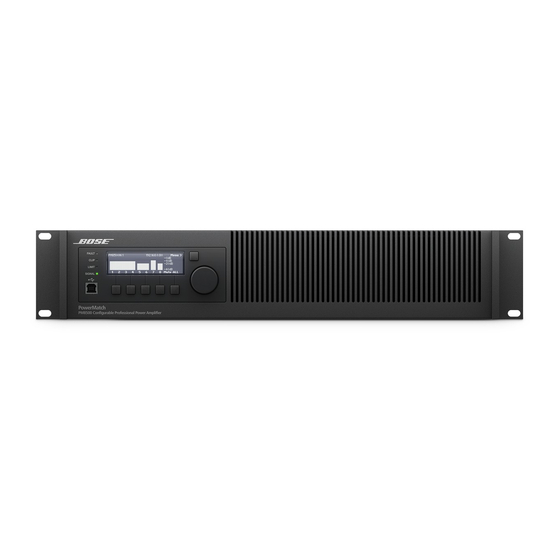
• PM8500 or PM8500N amplifier
• IEC-type detachable power cord
• Safety and Installation Guidelines document
• Connector Accessory Pack (contains eight (8) input connectors, two (2) output connectors, four (4) shorting jumpers,
one (1) Fault-Notification Output connector, and nine (9) plastic wire tie-wraps).
Rack Installation
The PM8500 is designed to fit standard 19-inch rack equipment, occupying 2 rack-units in height. Use four fasteners with washers
(not supplied) to mount the amplifier front-panel rack ears to the equipment rack rails. Rack-mount tabs are also provided on the rear
of the chassis to secure the amplifier to rear equipment rack rails with appropriate L-brackets (supplied by equipment rack vendor).
Ventilation
The PM8500 is designed for continuous operation with ambient temperatures of up to 40° C. However, to insure safe operation, the
front-panel, side and rear airflow vents should never be blocked. Air flows into the front of the unit and exits the rear and side vents. The
internal fans automatically increase speed when the amplifier is producing higher output power. Should the unit exceed safe operating
temperature, a gradual reduction of gain will automatically be applied for thermal protection. If the automatic gain reduction does not
reduce operating temperatures to safe conditions, the unit will mute all outputs and the red FAULT LED will illuminate on the front panel.
AC Mains Outlet Requirements
The PM8500 features a highly-efficient, universal switch-mode power supply with Power Factor Correction and can operate with AC
Mains line voltages from 100 to 240 volts at 50/60 Hz. With typical music program material, the PM8500 will provide full rated power
from a single 20-amp, 120V (common in USA) AC mains outlet, or single 16-amp, 230V (common in Europe) mains outlet.
Basic Wiring - Inputs
The balanced line-level analog inputs utilize 3-pin terminal block connectors (Phoenix #1776168 supplied). For balanced inputs, strip
the wire ¼ inch (6mm) and connect the respective positive, negative, and ground terminals as indicated on the unit and in Figure 6.
For unbalanced inputs, the connector should be wired with Pin 1 = positive, with Pin 2 and Pin 3 connected with a jumper wire and then
connected to the input cable shield.
Figure 6. Analog Input Connector
Pin 3
Pin 2
Pin 1
Basic Wiring – Fault Notification Output (Watchdog)
The PM8500 features a fault-notification circuit which outputs an electrical signal to a 3-pin terminal block connector (orange-color
Phoenix #1976010 supplied) Pin assignments are: Pin-1 = Normally Closed; Pin-2 = Common; and Pin-3 = Normally Open.
Figure 7. Fault Notification Output Connector
Pin 3
Pin 2
Pin 1
English
Installation and Safety Guidelines
Page 13