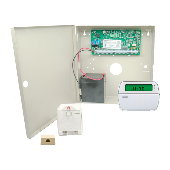
DSC PowerSeries PC1832 Manuale di installazione - Pagina 8
Sfoglia online o scarica il pdf Manuale di installazione per Pannello di controllo DSC PowerSeries PC1832. DSC PowerSeries PC1832 17. System
enhancement
module
Anche per DSC PowerSeries PC1832: Manuale di installazione (13 pagine), Manuale di installazione (20 pagine), Manuale (18 pagine)

Trouble
Trouble [5] Zone Fault (Cont.)
Trouble [6] Zone Tamper
Trouble [7] Wireless Device Low Battery
1st press – Wireless Zones
2nd press – Handheld Keypads
3rd press – Wireless Keys
Trouble [8] Loss of Clock/Date
Ensure you have the following information available before contacting Customer Support
- Control Panel Type and Version, (e.g., PC1864 v4.1)
NOTE: Version number can be accessed by entering [
also located on a sticker on the Printed Circuit Board.
- List of modules connected to Control Panel, (e.g., PC5400, PC5204 etc.)
Cause
One or more wireless devices have
not checked in within the
programmed time
A short circuit is present on one or
more zones with double end-of-line
resistors enabled
Press [6] to determine specific zones with a tamper trouble
A tamper condition is present on one
or more wireless devices
An open circuit is present on one or
more zones with double end-of-line
resistors enabled
Press [7] to toggle through specific devices with low battery trouble
One or more wireless devices has a
low battery
NOTE: The event will not be logged
to the event buffer until the wireless
device low battery delay time expires
• Program Section [377] Opt 9
The main panel internal clock is not
set
IMPORTANT!
✱
][Installer Code][900] on any system keypad. This information is
Troubleshooting
•
If the trouble occurs immediately, a conflict with a hard
wired zone exists:
• The zone being used is already assigned to a
PC5108 zone expander
• The zone being used is assigned as a keypad zone
•
Perform a Module Placement Test – Program Section
[904] and verify the wireless device is in a good location.
• If bad test results occur, test the wireless device in
another location
• If the wireless device now tests good, the original
mounting location is bad
• If the wireless device continues to give bad test
results replace the wireless device
•
Remove the wire leads from Z and COM terminals and
measure the resistance of the wire leads.
• A short circuit indicates a short in the wiring.
•
Connect a 5.6K resistor (Green, Blue, Red) across the Z
and COM terminals.
• Verify the trouble condition clears.
•
Perform a Module Placement Test –Section [904]
•
Violate, then restore the tamper:
• If no test result then replace wireless device
•
Remove the wire leads from Z and COM terminals.
•
Measure the resistance of the wire leads.
• Open circuit indicates a break in the wiring.
•
Connect a 5.6K resistor (Green, Blue, Red) across the Z
and COM terminals.
• Verify the trouble condition clears.
Replace battery
NOTE: Replacing batteries will cause a tamper. Replacing
cover will restore the tamper causing the associated report-
ing codes to be sent to the Central Station.
To program the time and date:
•
Enter [✱][6][Master Code] then Press [1]
or Press function key programmed with definition #26
•
Enter the time and date (in military) using the following
format: HH:MM MM/DD/YY
Example.
For 6:00 pm, June 29, 2005
Enter: [18] [00] [06] [29] [05]
