DSM VF-500 Manuale d'uso - Pagina 5
Sfoglia online o scarica il pdf Manuale d'uso per Amplificatore DSM VF-500. DSM VF-500 8. Voltage follower / linear amplifier for piezoelectric (capacitive) loads
114 Southeast Parkway Court, Suite 160
Franklin, TN 37064
Tel: 615/595-6665
Fax: 615/595-6610
Instructions for Use
Start-Up / Shut-Down Procedure
The VF-500 amplifier can be powered-up and powered-down with or without being connected to
an input signal. However, DSM recommends that the amplifier be connected to a load
(capacitive, such as a piezoelectric device of the appropriate rating) during start-up and while the
amplifier is running; operating without a load can be damaging to the amplifier's circuitry.
During start-up and shut-down, the output of the amplifier passes through some fast voltage
transients that quickly settle to zero volts (assuming there is no voltage on the input). These fast
voltage transients can cause the load (piezo actuator or stage) to move, and there can be an
audible noise that results from this fast motion. This is not damaging to the piezo element.
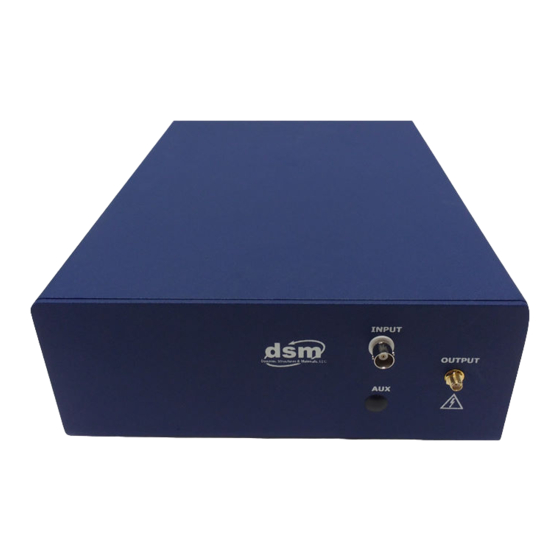
Connecting the Load to the Amplifier's Output
The VF-500 will have been configured at the factory for an output voltage range corresponding
to the specifications of the customer's load (one of the two types discussed in the "Intended Use"
section).
Attach a standard load (i.e. a piezoelectric actuator with two lead wires for signal and ground) to
the VF-500 via the OUTPUT SMA connector on the amplifier's front panel. Typically, the
piezoelectric material manufacturer will designate the "live" or "hot" electrode with red lead
wire and/or a visible mark on the piezo material to distinguish this electrode from the ground
electrode.
CAUTION: When the VF-500 is powered, the OUTPUT SMA connector of the amplifier
can carry voltages ranging up to 200V, depending upon the amplifier's configuration.
Power
Power for the VF-500 is provided through the standard receptacle located on the back panel of
the product enclosure. The power switch is located above the receptacle.
Input
Input to the unit (i.e. from a function generator) is made by a single BNC connector on the front
panel. This is a low-voltage only (-1.5V to +7.5V or -1.5 to +10V) input. Over-voltage input
beyond ±10V can damage the unit.
AC, DC, or superposed AC and DC signals (for example, from a computer D/A board) can be
used as input signals.
5