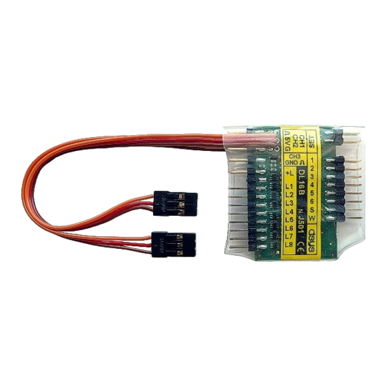
DSYS DL16B Manuale d'uso - Pagina 3
Sfoglia online o scarica il pdf Manuale d'uso per Apparecchiature di illuminazione DSYS DL16B. DSYS DL16B 12. Rc led lighting

Connect the S1 switch or the cable
plugged into the free channel of the
receiver to the CH3 connector.
Solder the wires to connector's counterparts. Cut the LEDs lead to 5mm
length, extend the leads with wires and isolate them properly.
The types and colours of used LEDs can be
combined.
LED polarity: flat side (usually shorter
lead) is negative (Cathode).
Powering LEDs from the Receiver (+5V). Connect the LEDs
cathodes to L1-L8 (A, B) connector pins. Connect the common
LED's anodes to +L (A, B). The + L (A, B) terminals are internally
connected. Do not connect any resistors to LEDs. The outputs
provide 20mA current.
You can connect one 3V LED (white, blue) or two red
2,1V LEDs. By connecting the K2 outputs (e.g. L1A with
L1B) the current
powerful LEDs !) You can connect any of L1-L8 A, B outputs.
When the voltage drops under 5V the LEDs light intensity decrease.
LED Powering from Driver Battery
Connect all LED anodes to positive (+) battery pole.
If you use standalone battery to power the LEDs then connect its
negative pole to the K1 connector G pin.
The maximum number of connected LEDs is determined by the
battery voltage per formula: Uaku -0,6-(n x Uled). Uaku= battery
voltage, 0,6V=stabilization, n=number of LEDs, Uled=LED voltage.
The calculated value must be between 0 - 5 (otherwise its overloaded).
Example 1. 8x NiMH (8 x 1,2 = 9,6V), 3 LED 2,1V in series.
Calculation: 9,6-0,6-(3 x 2,1) = 2,7. 3 LEDs can be used.
Example 2. 3S Li-Pol (3 x 3,7) = 11,1V), 4 LEDs 2,1V.
Calculation. 11,1 - 0,6 - (4 x 2,1) = 2,1. 4 LEDs can be used on one
output.
is increased to 40mA (Only for
(connection see page 4 - footlights).
Cable CH3
CH3
+A
-C
Switch S1
-C
+A
3
