3onedata IES215-2F-P Manuale di installazione rapida - Pagina 2
Sfoglia online o scarica il pdf Manuale di installazione rapida per Interruttore 3onedata IES215-2F-P. 3onedata IES215-2F-P 3. Unmanaged industrial ethernet switch
Note before mounting:
Don't place or install the device in area near water or
moist, keep the relative humidity of the device
surrounding between 5%~95% without condensation.
Before power on, first confirm the supported power
supply specification to avoid over-voltage damaging the
device.
The device surface temperature is high after running;
please don't directly contact to avoid scalding.
【DIN-Rail Mounting】
The product adopts 35mm standard DIN-Rail mounting which
is suitable for most industrial scenes, mounting steps as
follows:
Step 1
Check if the DIN-Rail mounting kit is installed firmly.
Step 2
Insert the bottom of DIN-Rail mounting kit (one side
with spring support) into DIN-Rail, and then insert
the top into DIN-Rail.
Tips:
Insert a little to the bottom, lift upward and then insert
to the top.
Step 3
Check and confirm the products is firmly installed
on DIN-Rail, then mounting ends.
【Disassembling DIN-Rail】
Step 1
Device power off.
Step 2
After lift the device upward slightly, first shift out the
top of DIN-Rail mounting kit, and then shift out the
bottom of DIN-Rail, disassembling ends.
Note before powering on:
Power ON operation: First insert the power supply
terminal block into the device power supply interface,
and then plug the power supply plug contact and power
on.
Power OFF operation: First, remove the power plug,
and then remove the wiring section of terminal block.
Please pay attention to the above operation sequence.
【Power Supply Connection】
DC power supply
The device provides 3-pin power supply input terminal blocks
and supports 1 DC power supply system which has
non-polarity and anti-reverse connection function, that the
device can work normally after reverse connection. Voltage
range: 12~48VDC.
AC power supply
The device provides 3-pin power supply input terminal blocks,
and supports 1 AC power supply. Power supply range:
100~240VAC/DC.
【DIP Switch Settings】
Provide 4 pins DIP switch for function settings, where "ON" is
enable valid terminal. DIP switches definition as follows:
DIP
Definition
Operation
1
Flow
Set the DIP to ON, copper port
control
supports IEEE802.1x flow control,
fiber port supports back pressure
flow control.
2
Specified
Set the DIP to ON, copper port rate
10M
would be forced to be in 10M full
duplex mode.
―
3
Reserved
―
4
Reserved
【Checking LED Indicator】
The device provides LED indicators to monitor the device
working
status
with
a
comprehensive
troubleshooting; the function of each LED is described in the
table as below:
LED
Indicate
ON
PWR
OFF
ON
Link/Act
(1-5)
Blinking
OFF
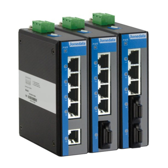
【Specification】
Panel
100M fiber port
100M copper port
Indicator
Switch Property
Backplane bandwidth
Packet buffer size
MAC Address Table
Power supply
Model I,
Model II,
Model III
Model IV,
Model V,
Model VI
Access terminal block
Power consumption
simplified
Description
PWR2 is connected and running
normally
PWR2
is
disconnected
and
running abnormally
The
Ethernet
interface
has
established an active network
connection.
The Ethernet interface is in a
network activity state.
Ethernet port has not established
valid network connection
100Base-FX,
optional
SC/ST/FC
10/100
Base-T(X)
self-adapting RJ45 port, full
duplex
or
half
duplex
self-adapting,
support
MDI/MDI-X self-adapting
Power
supply
indicator,
interface indicator
1.6G
1Mbit
2K
Support non-polar connection
100~240VAC/DC
4 pins 7.62mm pitch terminal
blocks