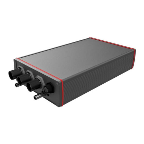
DTI HV-500 Descrizione tecnica - Pagina 11
Sfoglia online o scarica il pdf Descrizione tecnica per Inverter DTI HV-500. DTI HV-500 18.

HV-500 TECHNICAL DESCRIPTION
Motor sensor connector pinout (M)
Connector type: SOURIAU UTS712D14S32
Harness side connector type: SOURIAU UTS6JC12E14P
A
B+ / Hall U
B
B-
C
A+ / Hall V
D
Z-
E
TEMP
F
GND
H
A- /
J
Z+ / Hall W
K
+5 V
L
GND
M CLK+
N
DATA-
P
DATA+
R
CLK-
INCREMENTAL ENCODER + SSI
•
Compatible with normal or differential signals.
•
±15 kV ESD-Protected signals
•
Maximum input signal voltage: 5 V
•
Maximum encoder resolution: 4096 (counts per revolution)
•
Maximum input frequency: 400 Khz
Usable encoders: RLS RM44SI,
Revision 1.31
(BETA
R
H
M
A
4
L
4
L
ABI encoder „B" differential signal positive or A hall sensor
ABI encoder „B" differential signal negative
ABI encoder „A" differential signal positive or B hall sensor
ABI encoder „Z" differential signal negative
Temperature sensor
Temperature sensor ground
ABI encoder „A" differential signal negative
ABI encoder „Z" differential signal positive or C hall sensor
Encoder or hall sensor supply output
Encoder or hall sensor ground
ABI encoder SSI „CLK" differential signal positive
ABI encoder SSI „DATA" differential signal negative
ABI encoder SSI „DATA" differential signal positive
ABI encoder SSI „CLK" differential signal negative
Sensor connection diagram
VERSION)
11
