AIRTRONICS SD-10G Aero Manuale - Pagina 6
Sfoglia online o scarica il pdf Manuale per Telecomando AIRTRONICS SD-10G Aero. AIRTRONICS SD-10G Aero 16. 2.4ghz fhss-3 radio control system
Anche per AIRTRONICS SD-10G Aero: Manuale di configurazione rapida (8 pagine), Manuale di avvio rapido (5 pagine)

glossary of terms
Model Name: The Model Name function allows you to name each of your individual models. This makes it easy to keep track of
multiple models. The Model Name can consist of up to 8 letters, numbers, or symbols. Choose from capital letters, lower case
letters, numbers, and various symbols.
Model Select: The Model select function allows you to load the programming for the particular model you wish to fly. The
programming for all of your models is accessed through the Model Select menu.
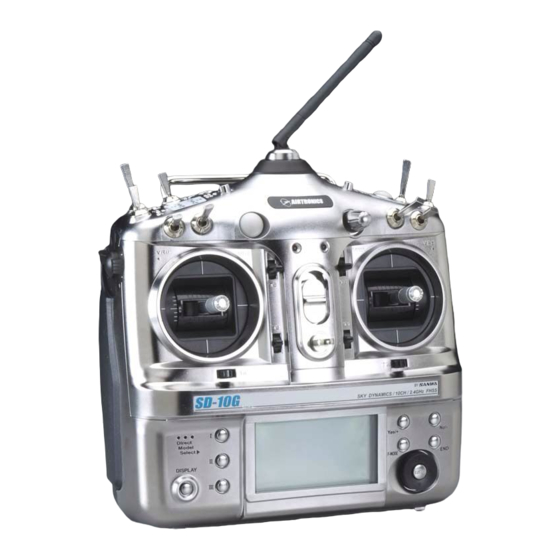
Navigation Pad: The Navigation Pad is used in conjunction with the Programming Keys and the F-MODE Key to facilitate
transmitter programming. The Navigation Pad allows you to quickly and easily move the Programming Cursor up and down, and
right and left. The ENTER Key in the center of the Navigation Pad is used to open the selected menu or programming option.
NiMH: Short for Nickel Metal Hydride, the NiMH battery typically has about two to three times the capacity of an equivalently
sized Ni-Cd (Nickel Cadmium) battery, therefore, they are ideal for use to power both the transmitter and the receiver. The
SD-10G transmitter features a 6 cell 1500mAH NiMH battery for light weight and long usage time.
Operating Voltage: The safe voltage that the transmitter or receiver can operate within. Exceeding the minimum operating voltage
can result in loss of power to the device(s). Exceeding the maximum operating voltage can result in damage to the devices(s).
Output Power: The power (in Milliwatts) that your transmitter transmits a signal. Output power is defined by government
guidelines and differs by region.
Pitch Curve: The Pitch Curve function allows you to vary the amount of pitch travel in relation to the movement of the throttle
control stick at different points throughout the entire range of deflection.
Power Switch: Turns the transmitter ON and OFF.
PPM8 Modulation: A modulation type that is strictly used only when using the SD-10G transmitter with a computer-based flight
simulator. Using this modulation allows the transmitter to communicate with your computer's flight simulator software.
Programming Keys: The Programming Keys are used in conjunction with the Navigation Pad and the F-MODE Key to facilitate
transmitter programming. The three Programming Keys consist of the YES/+ (Increase) Key, the NO/- (Decrease) Key, and the
END Key.
Push-Button Switch: Two Push-Button Switches are featured. Each Push-Button Switch is programmable and will perform a
different function depending on what function is assigned to it.
Reflex: Reflex is typically used on sailplanes and refers to the function of raising the entire trailing edge of the wing to change
airfoil of the wing, and therefore, the flight characteristics of your aircraft. Reflex is typically used during high-speed flight to
increase speed. Reflex is also commonly used on delta wing aircraft that use elevon mixing for control.
RF Output Indicators: Both indicators illuminate when the transmitter is turned ON and transmitting a signal. If one or both of
the RF Output Indicators fails to illuminate, RF output is limited or non-existent. In this case, you should not fly.
Rhythm Timer: The Rhythm timer can be programmed to provided a selected sequence of audible tones, which can be used for
pacing aerobatics or for practicing precision landings. Three separate Rhythm timers can be programmed and each Rhythm timer
can be turned ON separately by assigning them to different switch positions. Each Rhythm timer features five programmable
Types. Within each Type, the Start time, the Interval time, the Sound, and the Count can be programmed individually. This allows
for a near infinite combination of audible tones to suit nearly any situation.
Safety Link: The Safety Link function is used to program a unique bind code to each receiver/model pair, preventing the transmitter
from controlling a model that it's not currently programmed for. In addition, the Safety Link Number can be changed separately from
the Model Select number to allow you to bind multiple receivers to the same model. The Safety Link feature can be used ONLY with
the Airtronics 92104 10-Channel 2.4GHz FHSS-3 receiver. Safety Link is not supported for use with Airtronics FHSS-1 receivers.
Servo Monitor: The Servo Monitor function displays the output levels of the four different channels in bar graph form, allowing
you to monitor servo operation in a virtual manner. Using the Servo Monitor function while making setting changes can make it
easier to understand the setting changes you're making.
Servo Reversing: Electronically switches the direction of servo travel. For example, if you move the elevator control stick
forward, and the elevator moves up, you can use the Servo Reversing function to make the elevator move down.
Servo Centering: The Centering function allows you to fine-tune the Center (Neutral) position of each servo. It's not unusual
that when you install the servo horn onto your servo that the servo horn is not perfectly centered. Centering allows you to center
the servo horn perfectly.
Servo Limits: The Limits function allows you to set a hard limit for servo travel in each direction (H - High or L - Low). This means
that regardless of the End Point Adjustment, Dual Rate, and/or Mixing Adjustment Values programmed, the servo will never rotate
past the specified Limits. Limits should be used to Limit the maximum required physical travel of the servo in each direction, so
that the servo can never rotate further than intended.
Page 198
