Abstract Data ADE-51 Manuale d'uso - Pagina 7
Sfoglia online o scarica il pdf Manuale d'uso per Unità di controllo Abstract Data ADE-51. Abstract Data ADE-51 12. Vc ahdsr/ahd envelope generator

5) Inputs & Outputs
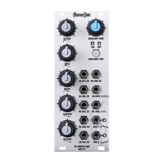
1) IN: ATT. CV
A CV signal at this input enables external control over the time of the Attack stage of the envelope.
ADE-51 CV inputs are designed to take a 0-5V CV signal. CV signals outside of the 0-5V range
(<0V and >5V) will be blocked by the final output of the CV circuit - but please try to ensure that
the CV signals used are generally within the Eurorack standard.
ADE-51 CV inputs work with their associated pot to provide an initial CV bias level. Positive CV
signals are added to and negative signals are subtracted from the initial CV bias level allowing the use
of attenuated, AC and (Low Frequency Oscillator) LFO signals to provide a full range of modulation.
2) IN: HOL. CV
A CV signal at this input enables external control over the time of the Hold stage of the envelope.
3) IN: DEC. CV
A CV signal at this input enables external control over the time of the Decay stage of the envelope.
4) IN: SUS. CV
A CV signal at this input enables external control over the level of the Sustain stage of the envelope.
5) IN: REL. CV
A CV signal at this input enables external control over the time of the Release stage of the envelope.
6) IN: ENV. CV
A CV signal at this input enables external control of the overall time of the entire envelope.
7) IN: GATE [AHDSR]
The Gate input will accept a Gate, Trigger, Pulse, Clock or any positive-going signal with a fast,
rising edge. Any signal of this type at this input will cause the 5-stage AHDSR envelope to generate.
The ADE-51 Gate input uses the standard envelope generation method where the Release stage is
triggered as soon as the input signal goes low.
8) IN: TRIG [AHD]
The ADE-51 Trigger input has dual functionality. When used in conjunction with Gate triggering of
5-stage AHDSR envelopes - it acts as a re-Trigger input, causing the envelope to start
generating again from the Attack stage (see Page 8).
Any re-Trigger signal received after the Attack and Hold stages have completed while the Gate signal
is still 'High' will cause the Envelope to re-Trigger from the CV level the envelope was at when the
re-Trigger was received (see Page 8).
Used by itself - it will Trigger a 3-stage AHD envelope that operates independently of the Trigger length.
Here - the Attack time operates normally, the length of the 'Sustain' stage is determined by the Hold
control at a full +5V and the 'Release' stage of the envelope is set by the Decay control (see Page 8).
9) OUT: 1
Standard envelope output in a 0-5V range.
10) OUT: 2
Inverted envelope output in a 5-0V range.
© 2017 Abstract Data Ltd.
Page 5 of 9
Version 1.0.2
