3onedata TNS5500D Series Manuale di installazione rapida - Pagina 3
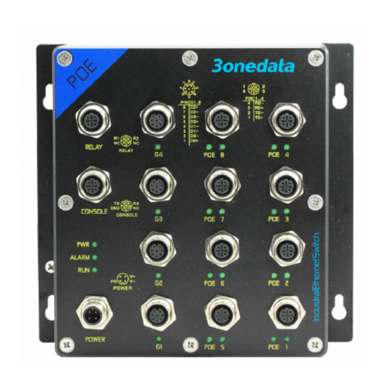
Sfoglia online o scarica il pdf Manuale di installazione rapida per Interruttore 3onedata TNS5500D Series. 3onedata TNS5500D Series 3. 12-port series layer 2 wall mounting industrial ethernet switch
Anche per 3onedata TNS5500D Series: Manuale di installazione rapida (4 pagine), Manuale di installazione rapida (4 pagine), Manuale di avvio rapido (5 pagine)
1
TD+
Positive send data of
100M Ethernet
2
RD+
Positive receive data of
100M Ethernet
3
TD-
Negative send data of
100M Ethernet
4
RD-
Negative receive data of
100M Ethernet
【Checking LED Indicator】
The series of devices provide LED indicators to monitor its
operating status, which has simplified the overall
troubleshooting process. The function of each LED is
described in the table below:
LED
Indicate
Description
PWR is connected and running
ON
normally
PWR (X1)
PWR is disconnected and
OFF
running abnormally
The device is powering on or
ON
the device is abnormal.
The device is powered off or
RUN
OFF
the device is abnormal
Blinking 1 time per second,
Blinking
system is running normally
ON
Port link has alarm
ALM
OFF
Port link has no alarm
Ethernet port has established a
ON
valid network connection
Ethernet port is in an active
Link
Blinking
network status
(X11-X18)
Ethernet
OFF
established
connection
【Logging in to WEB Interface】
This device supports WEB management and configuration.
Computer can access the device via Ethernet interface. The
way of logging in to device's configuration interface via IE
browser is shown as below:
Configure the IP addresses of computer and the
device to the same network segment, and the
network between them can be mutually accessed.
Enter device's IP address in the address bar of the
computer browser.
Enter device's username and password in the login
window as shown below.
Click "OK" button to login to the WEB interface of
the device.
Note:
The default IP address of the device is "192.168.1.254".
The default user name and password of the device are
"admin".
If the username or password is lost, user can restore it to
factory settings via management software; all modified
port
has
not
configurations will be cleared after restoring to factory
valid
network
settings, so please backup configuration file in advance.
Please refer to user manual for specific configuration
method of logging in to WEB interface and other
configurations about network management function.
【Specification】
Panel
Power supply interface
M12(Male), 4-Pin A-Coded, the
power supply occupies two
pins, V- and V+
Relay interface
M12 (Male), 4-Pin A-Coded, the
relay occupies two pins,
RELAY1 and RELAY2
100M Ethernet port
10/100Base-T(X), M12(Female)
4-Pin D-Coded, Automatic Flow
Control, Full/Half Duplex Mode,
MDI/MDI-X Autotunning
Service debugging port
M12 (Female), 4-Pin A-Coded
Indicator
Power
indicator,
interface indicator
Switch Property
Backplane bandwidth
7.6G
Cache size
1Mbit
MAC address table
8K
Power Supply
M12 A-Coded 4-Pin (male)
connector
Model I: 110VDC
Input power supply
(66~154VDC)
Model II: 24VDC
(9~36VDC)
Power Consumption
No-load
2.1W@24VDC
Full-load
3.8W@24VDC
Working Environment
Working temperature
-40 ~ 75℃, in which working
≥10 minutes at 85℃
Storage temperature
-40~85℃
Working humidity
5%~95% (no condensation)
Protection grade
IP67(metal shell)
indicator,
running
alarm
indicator,