Concoa 526 **3 Series Manuale di istruzioni per l'installazione e il funzionamento - Pagina 8
Sfoglia online o scarica il pdf Manuale di istruzioni per l'installazione e il funzionamento per Strumenti di misura Concoa 526 **3 Series. Concoa 526 **3 Series 17. Automatic switchover system for use with non-toxic and non-corrosive gases in high purity applications
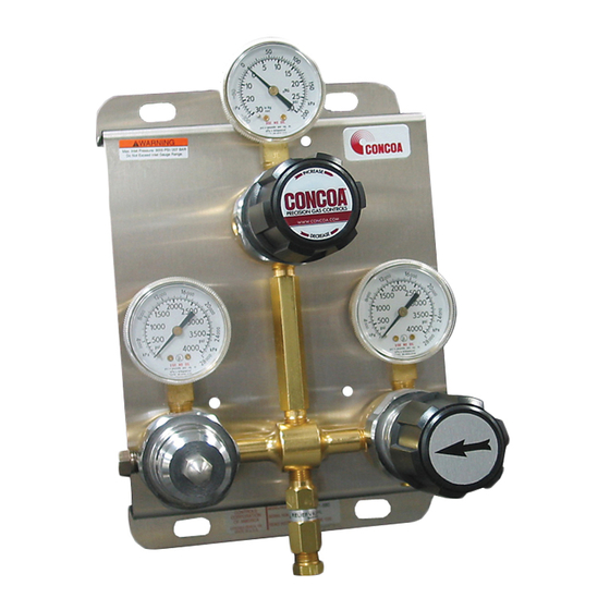
Mount the switcho ver system to a fl at surface us ing the
4.37 in (111 mm)
appropriate hardware at hole locations provided in the
bracket. Dimensions for these holes are shown Figure 3.
If installing to a 528 Series Manifl ex manifold, follow the
instructions provided with the manifold. If installing for
use with cylinders, provide enough clearance between
the top of the cylinder and the switchover system. The
typical installation for high-pressure cylinders needs 66
inches between the fl oor and the "INLET" port.
Install inlet and outlet connections to the regulator. Use an
open-end wrench, not a pipe wrench, to install ac ces so ries
to the autoswitch system. ¼" NPT connections require
the use of PTFE tape on the threads to make a gas tight
seal. On stainless steel connections, the thread sealant
helps prevent the connections from galling together when
tightening or loosening. CONCOA uses PTFE tape on
all of its regulator NPT con nec tions. Follow these rules
when using PTFE tape.
Figure 3 - Installation Bracket
.88 in (22 mm)
Inspect the NPT threads and if necessary, clean the fi tting to remove any dirt or thread sealant that remains
on the threads. Start the PTFE tape on the second thread as shown in Figure 4; make sure the tape does
not overlap the end of the fi tting. As the tape is wrapped in the direction of the thread spiral, pull tightly on
the end of tape so that the tape conforms to the threads. Wrap the tape around the threads twice. Cut off
the excess tape and press the end fi rmly into the threads. (See Figure 4 below.)
Figure 4. PTFE Tape Placement
8