AnyTone AT-5555 PLUS Manuale di istruzioni - Pagina 8
Sfoglia online o scarica il pdf Manuale di istruzioni per Radio AnyTone AT-5555 PLUS. AnyTone AT-5555 PLUS 17. 10 meter radio

it is desired that the control be adjusted only to the point where the
receiver background noise or ambient background noise is eliminated.
Turn fully anticlockwise then slowly clockwise until the receiver noise
disappears. Any signal to be received must now be slightly stronger
than the average received noise. Further clockwise rotation will
increase the threshold level which a signal must overcome in order to
be heard. Only strong signals will be heard at a maximum clockwise
setting.
3. ECHO(Inner Dual Concentric)
This switch is used to control echo effect.
4. TONE (Outer Dual Concentric)
This switch is used to control intervals of echo sound
5. RF GAIN ( Inner Dual Concentric)
This switch is for adjusting sensitivity during reception. For long
distance communications RF GAIN should be set to maximum. RF
GAIN can be reduced to avoid distortion, when your correspondent is
5
close by and when he does not have RF POWER. The normal setting
of this function is on maximum (fully clockwise).
6. RF POWER (Outer Dual Concentric)
Adjustment of the output power is for AM and FM mode only. Reducing
the power is allowed when communicating with a person who has no
RF GAIN. The normal position of this function is set to maximum, fully
clockwise.
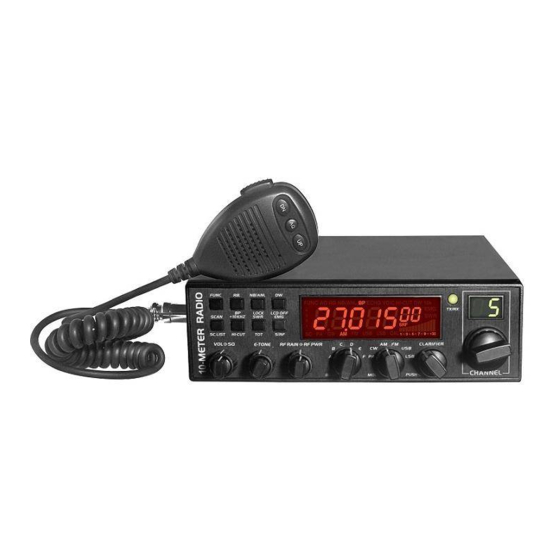
7. BAND SELECTOR
Rotate this switch to select A, B, C, D, E, F band of operation
8. MODE(PA/CW/AM/FM/USB/LSB)
This switch allows selecting the modulation mode PA, CW, AM, FM,
LSB or USB. Your modulation mode has to correspond with the one
of your correspondent. The mode selector changes the mode of
operation of both transmitter and receiver simultaneously.
Frequency Modulation/FM: for nearby communications on a flat
open field.
Amplitude Modulation/AM: Communication on a field with relief and
obstacles in middle distance (the most used).
Upper and Lower Side Band/USB-LSB: Used for long distance
communications (according to the propagation conditions).
9. CLARIFIER
This is frequency tuning knob which can be set as different modes
(refer to CLA Specifications in Functions Menu for more details).
10. PUSH
This is PUSH Key which can be set as different modes (refer to PSH
specifications under Functions Menu for more details).
11. CHANNEL SELECTOR
Rotate this switch to select any desired channel from forty citizens
band channels. The selected channel appears on the LED directly
above the channel selector knob.
12. CHANNEL INDICATOR
Numbered LED indicates the selected channel to operate on.
13. RECEIVER/TRANSMIT INDICATOR
When it is receiving, the LED will be green. The LED will be red when
it is transmitting.
14. LCD DISPLAY
Display frequency, all kinds of information and icons.
15. FUNC
This is functional key. Press and hold this key for 2seconds to enter
into Functions Menu Setup (refer to Functions Menu for more details).
Press FUNC key and other individual key to realize the second
functions silk-screened under the button. For example, press FUNC
key followed by pressing RB key to realize the BP function. Press
FUNC key followed by DW to realize the LCD OFF function.
Details operations are as bellows:
Press FUNC key, "FUNC" icon will appear on LCD display. Release
