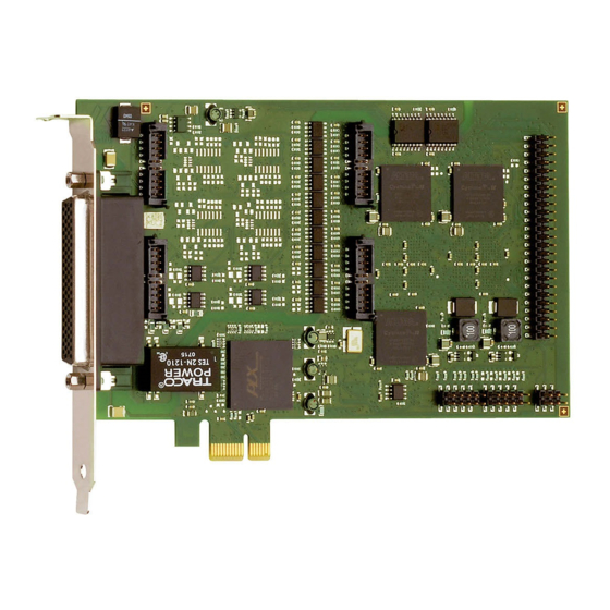
Addi-Data APCI-1710 Descrizione della funzione - Pagina 11
Sfoglia online o scarica il pdf Descrizione della funzione per PCI Card Addi-Data APCI-1710. Addi-Data APCI-1710 15. Multifunction counter board, optically isolated
Anche per Addi-Data APCI-1710: Descrizione della funzione (17 pagine), Manuale (13 pagine)

Function description
Signal generator
Lead colour
Pin No.
Pin name
+24 V / U
Ref
GND
x = Number of the function module (0-3)
www.addi-data.com
Table 1-3: Connection of the signal generators to the screw terminal panel
Terminal
Signal name
(cable)
name
+24 V / U
+24 V / U
Ref
GND
GND
DIG_IO_Ax+
Ax+
DIG_IO_Ax-
Ax-
DIG_IO_Bx+
Bx+
DIG_IO_Bx-
Bx-
DIG_IN_Cx+
Cx+
DIG_IN_Cx-
Cx-
DIG_IN_Dx+
Dx+
DIG_IN_Dx-
Dx-
DIG_IN_Ex
Ex
DIG_IN_Fx
Fx
DIG_IN_Gx
Gx
DIG_OUT_Hx
Hx
-
-
-
-
** APCIe-/CPCIs-1711: 5-36 V, APCI-/CPCI-1710 10-36 V
Screw terminal panel PX8001 (50-pin)
Terminal No.
Signal type
FM0
FM1
-
34
34
Ref
-
1
Diff./TTL/24 V*
2
10
Diff./TTL/24 V*
3
11
Diff./TTL/24 V*
4
12
Diff./TTL/24 V*
5
13
Diff./TTL/24 V*
6
14
Diff./TTL/24 V*
7
15
Diff./TTL/24 V*
8
16
Diff./TTL/24 V*
9
17
24 V / opt. 5 V
39
40
24 V / opt. 5 V
43
44
24 V / opt. 5 V
47
48
24 V**
35
36
-
-
-
-
-
-
-
-
-
-
-
-
11
Terminal function
FM2
FM3
see Technical Description
34
34
of the board
1
1
1
Ground
18
26
Digital input/output
(only input with 24 V*)
19
27
20
28
Digital input/output
(only input with 24 V*)
21
29
22
30
Digital input
23
31
24
32
Digital input
25
33
41
42
Digital input
45
46
Digital input
49
50
Digital input
37
38
Digital output
-
-
-
-
-
-
-
-
-
-
-
-
-
-
-
-
* 24 V with 24 V board version
Digital I/O
