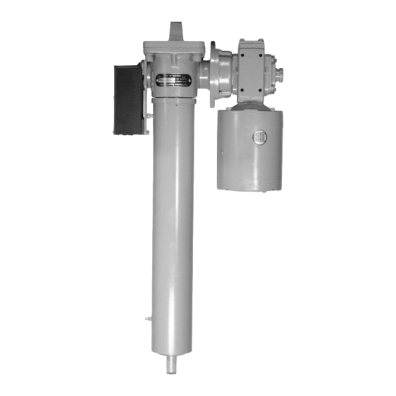
Duff-Norton SuperCylinder Series Istruzioni per l'installazione, il funzionamento e la manutenzione - Pagina 9
Sfoglia online o scarica il pdf Istruzioni per l'installazione, il funzionamento e la manutenzione per Controllore Duff-Norton SuperCylinder Series. Duff-Norton SuperCylinder Series 12. Linear actuators

Index
No
Part Name
1
Shell
2
Load bearing
3
Worm gear
4
Screw bushing
5
Lock nut
6
Screw
7
Key
8
Stop disc
9
Stop bolt
10
Lifting nut
11
Nut guide
12
Spiral ring
13
Translating tube
14
Setscrew
15
Wiper seal
Figure 5-1. Exploded Illustration for Duff-Norton
SuperCylinder Series
Qty.
Index
Req.
No
1
16
Retaining ring
2
17
Guide bushing
1
18
Outer tube
1
19
Shell (adapter) cap
5
20
Setscrew
1
21
Setscrew
1
22
Vent
1
23
Grease fitting
1
24
Grease seal
1
25
Flange
1
26
Worm bearing
2
27
Worm
1
28
Clevis bracket
1
29
Screw
1
Qty.
Part Name
Req.
1
1
1
1
1
1
1
2
2
2
2
1
1
4
Warning
Use only replacement
parts supplied by or
approved by Duff-Norton.
Non-authorized parts may
be inadequate, resulting
in serious injury or death
in event of failure.
9
