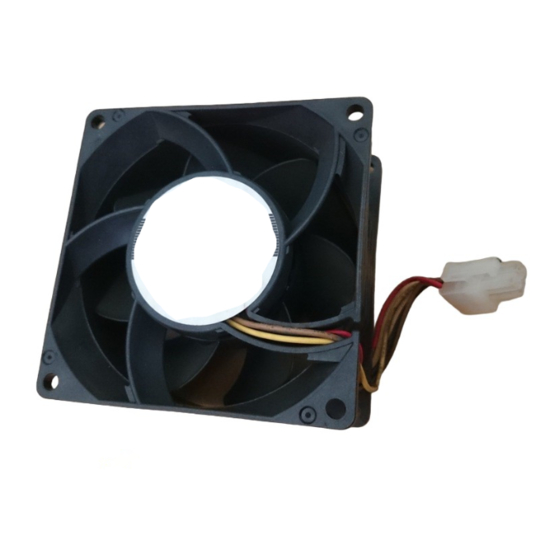
Danfoss 176F3167 Manuale di applicazione - Pagina 2
Sfoglia online o scarica il pdf Manuale di applicazione per Azionamenti in corrente continua Danfoss 176F3167. Danfoss 176F3167 8. Top fan kit for fa09-fa12/d3h-d4h/e3h-e4h

Top Fan Kit for FA09-FA12/D3h-D4h/E3h-E4h
Application Guide
2 Installation
2.1 Safety Information
QUALIFIED PERSONNEL
Only qualified, Danfoss authorized personnel are allowed to install the parts described in these installation instructions.
-
Disassembly and reassembly of the frequency converter must be done in accordance with the service guide.
-
Use the standard fastener torque values from the service guide, unless the torque value is specified in these instructions.
ELECTRICAL SHOCK HAZARD
Danfoss frequency converters contain dangerous voltages when connected to mains voltage. Improper installation, and instal-
ling or servicing with power connected, can cause death, serious injury, or equipment failure.
-
Only use qualified electricians for the installation.
-
Disconnect the frequency converter from all power sources before installation or service.
-
Treat the frequency converter as live whenever the mains voltage is connected.
-
Follow the guidelines in these instructions and local electrical safety codes.
DISCHARGE TIME
The frequency converter contains DC-link capacitors, which can remain charged even when the frequency converter is not pow-
ered. High voltage can be present even when the warning LED indicator lights are off. Failure to wait the specified time after
power has been removed before performing service or repair work can result in death or serious injury.
-
Stop the motor.
-
Disconnect AC mains and remote DC-link power supplies, including battery back-ups, UPS, and DC-link connections to other
frequency converters.
-
Disconnect or lock the motor.
-
Disconnect any brake option.
-
Disconnect any regen/load share option.
-
Wait for the capacitors to discharge fully. The minimum waiting time is listed on the frequency converter label and also in the
following discharge time table.
-
Before performing any service or repair work, use an appropriate voltage measuring device to make sure that the capacitors
are fully discharged.
Table 4: Discharge Time
Frame
D1h–D8h
Fx09–Fx10
E1h–E4h
Fx11–Fx12
2 | Danfoss A/S © 2022.03
N O T I C E
W A R N I N G
W A R N I N G
Minimum waiting time
20 minutes
20 minutes
40 minutes
40 minutes
Installation
AN389655468601en-000101 / 130R0767
